
Fabrication method for laminated-type secondary battery

A secondary battery and manufacturing method technology, applied in the direction of secondary batteries, batteries, battery pack components, etc., can solve the problems of shortening the forming cycle, shortening the production cycle, increasing costs, etc., and achieve the effect of promoting cooling and shortening the production cycle

Active Publication Date: 2014-06-18
ENVISION AESC JAPAN LTD
View PDF5 Cites 3 Cited by
  • Summary
  • Abstract
  • Description
  • Claims
  • Application Information

AI Technical Summary

Problems solved by technology

As a result, there is a limit to shortening the molding cycle per shot when mass-producing laminated secondary batteries.
[0004] In addition, although the releasability from the mold can be improved to some extent by using a release agent, there is a limit to shortening the production cycle by increasing the application of the release agent, and it is unavoidable to increase the cost, so it is not preferable. of

Method used


Image

  • Fabrication method for laminated-type secondary battery
  • Fabrication method for laminated-type secondary battery
  • Fabrication method for laminated-type secondary battery

Examples


Embodiment Construction

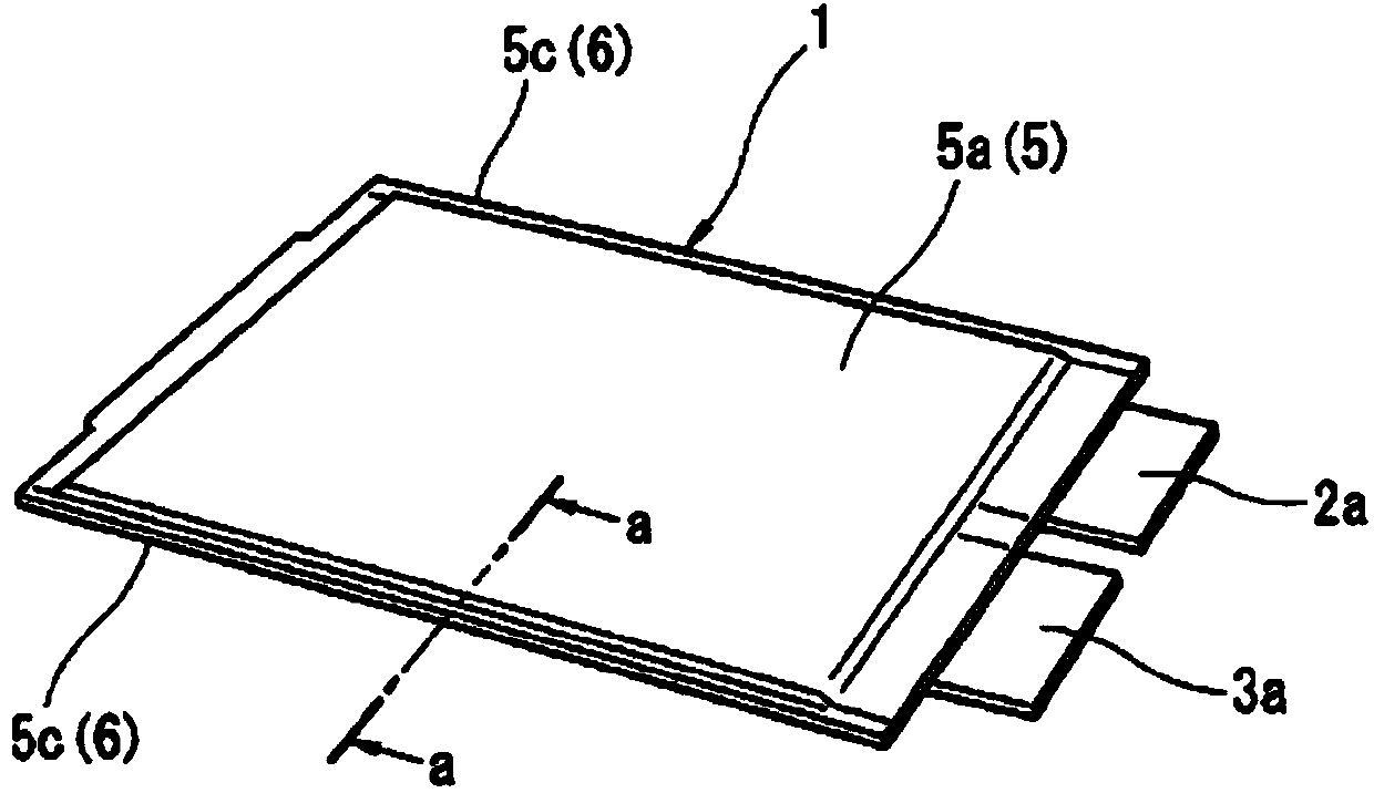
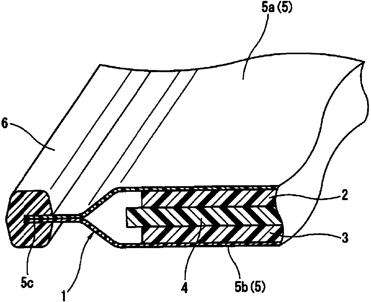
[0018] figure 1 The following drawings represent more specific embodiments for carrying out the present invention, especially figure 1 It shows the appearance shape of a thin laminated lithium ion secondary battery (hereinafter referred to as "battery") as an example of a laminated secondary battery to be manufactured, figure 2 yes means figure 1 An enlarged cross-sectional view along line a-a of . Furthermore, the battery described above is used, for example, as a battery cell of a lithium-ion storage battery for an electric vehicle.

[0019] Such as figure 1 , figure 2 As shown, the battery 1 is packaged by a rectangular-shaped laminated film outer case 5, and the laminated film outer case 5 is formed from upper and lower sides so that the positive terminal 2a and the negative terminal 3a protrude outward. Composed of laminated films 5a, 5b, the positive electrode 2, negative electrode 3, and separator 4 as battery elements are packaged inside the laminated film o...


PUM


Abstract

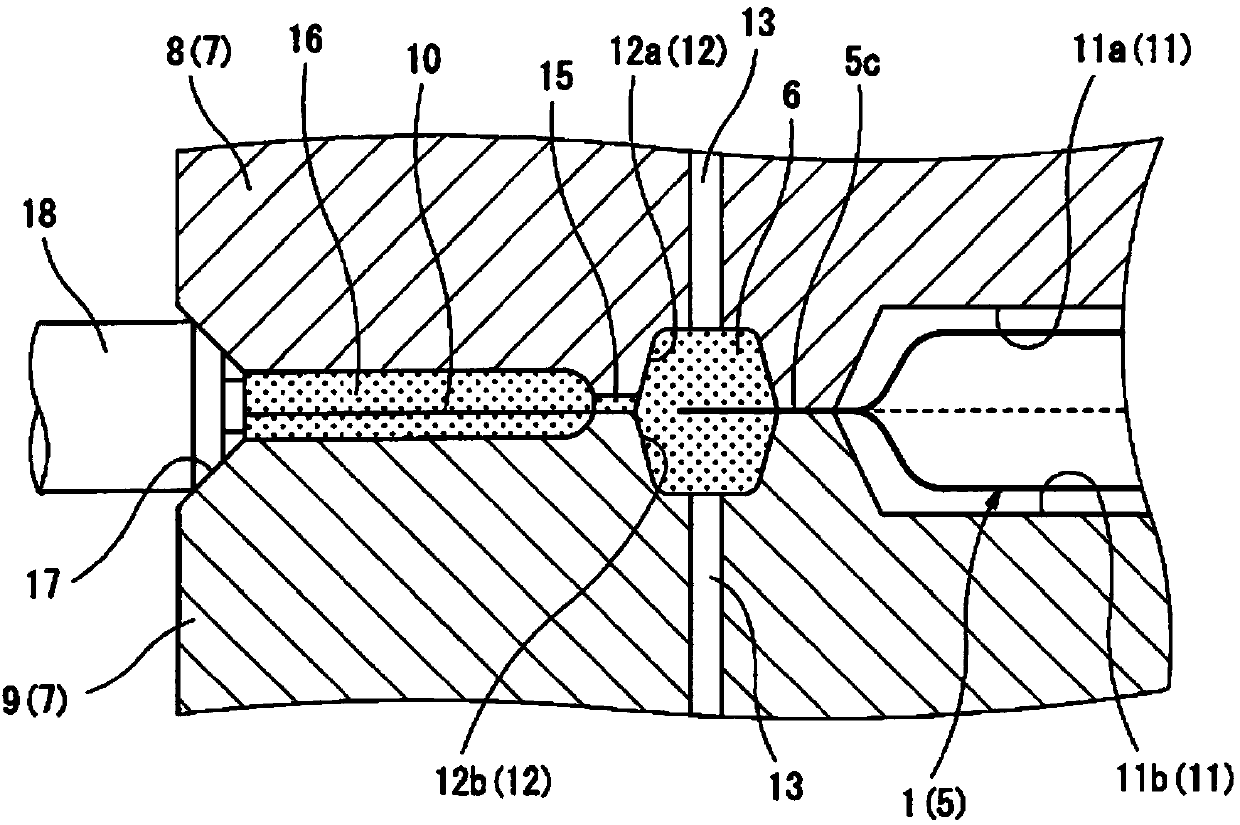
In the present invention, after filling or injecting a hot melt resin material into a product shaped space (12) in a metal mold (7) and before the hot melt falls below the softening point, compressed air from an air ejection port (14) is injected between the mold that isolates the product shaped space (12) and the surface of the hot melt resin layer. By means of the injection of compressed air, a "regress" is forcibly generated on the surface of the edge protector (6) thereby forming a concave section (Q), and at the same time a space (G) is formed between the hot melt and the mold surface. By doing this, the bead-shaped edge protector (6) is integrally formed by the thermoplastic hot melt resin material at a long-side thermal bonding part (5c) of a laminated-film housing case (5), thus improving mold releasability.

Description

technical field [0001] The present invention relates to a method for manufacturing a laminated secondary battery (battery pack or assembled battery), and more specifically, relates to a method for bonding a rib-shaped edge protector to a laminate containing battery elements using a hot-melt adhesive. A method of integrally molding the peripheral portion of a film exterior body. Background technique [0002] As a structure of such a laminated secondary battery pack, a structure is known in which, for example, as described in Patent Document 1, a battery element composed of a positive electrode, a negative electrode, and a separator is housed in a laminated film outer casing together with an electrolytic solution. And sealing is performed, and the periphery of the laminated film exterior body is airtightly covered with a hot-melt resin, preferably an ionomer resin, to form a frame for reinforcement. [0003] When manufacturing a stacked type secondary battery as described in ...

Claims


Application Information

Patent Timeline
Patent Type & Authority Applications(China)
IPC IPC(8): H01M2/02B29C45/14B29C45/40H01M50/103H01M50/119H01M50/121H01M50/124
CPCB29C45/561H01M2/028H01M2200/20H01M10/0525B29C45/174H01M2/029H01M2/0262Y02T10/7011Y02E60/122H01M10/0585H01M50/119H01M50/103H01M50/121H01M50/124B29C45/40B29C45/43B29C2949/00B29K2105/0067Y02E60/10Y02P70/50Y02T10/70B29C49/00H01M2220/20
Inventor 落合健一北川信一郎澁谷雅一
Owner ENVISION AESC JAPAN LTD
Learn More