Oscillation apparatus
A technology of oscillation device and oscillation circuit, which is applied in the direction of power oscillator, output stability, automatic power control, etc., can solve the problems that the technology of frequency stability improvement has not been recorded, and achieve the effect of oscillation frequency stability
- Summary
- Abstract
- Description
- Claims
- Application Information
AI Technical Summary
Problems solved by technology
Method used
Image
Examples
no. 1 Embodiment approach )
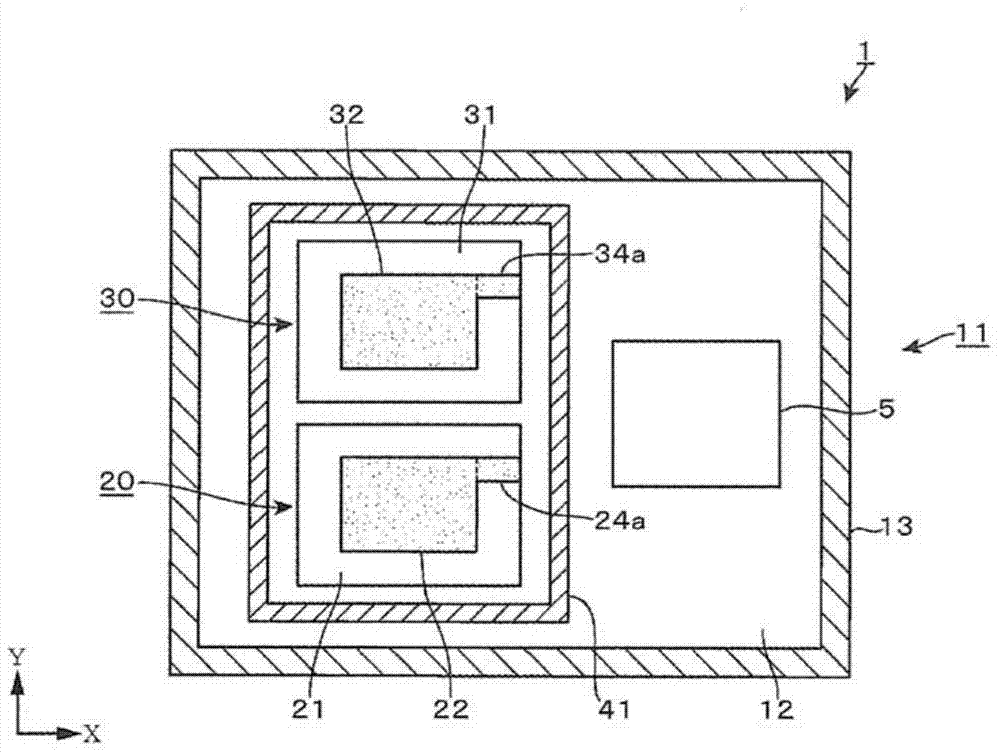
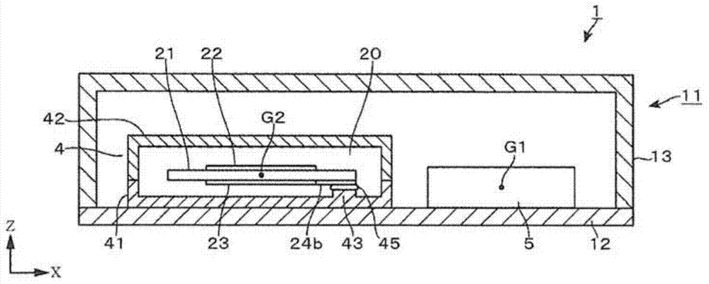
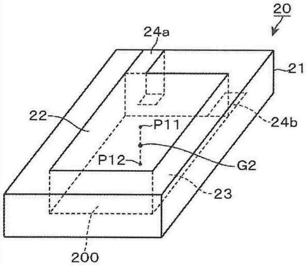
[0098] figure 1 A first embodiment of a crystal oscillator as an oscillation device of the present invention is shown. figure 1 is the plan view of the oscillatory device, figure 2 It is a longitudinal sectional side view of an oscillation device. In addition, X, Y, and Z in the figure are the coordinate axes of the rectangular coordinate system. figure 1 Reference numeral 11 is a container including a printed circuit board 12 and, for example, a cover 13 made of ceramics, and on the upper surface side of the printed circuit board 12, a package 4 for accommodating the following crystal resonators 20 and 30 and a package including the crystal resonator 20 are provided. An integrated circuit chip (IC chip) 5 ie an LSI formed by converting a digital processing circuit into one chip, such as an oscillation circuit and a frequency difference detection unit of , 30 .
[0099] The crystal resonators 20 and 30 will be described. Symbols 21 and 31 in the figure are, for example...
no. 2 Embodiment approach )
[0116] The difference between this embodiment and the above-mentioned embodiment is that: Image 6 and Figure 7 As shown, the IC chip 5 is provided on the back side of the printed circuit board 12 so as to face the package 4 . The package 4, the first crystal resonator 20, the second crystal resonator 30, and the like are configured in the same manner as in the first embodiment. The same reference numerals are assigned to the same components as those in the first embodiment, and description thereof will be omitted.
[0117] The package 4 is mounted on one side of the printed circuit board 12 with solder, and the IC chip 5 is mounted on the other side of the printed circuit board 12 with solder. The first excitation electrodes 22 , 23 and the second excitation electrodes 32 , 33 are symmetrically arranged in the container 11 . In addition, the IC chip 5 is formed in a bilaterally symmetrical shape with respect to a straight line S that is spaced equidistantly from the cente...
no. 3 Embodiment approach )
[0123] In this embodiment, the oscillator of the present invention is applied to an oscillator with a constant temperature bath (OCXO). Figure 9 and Figure 10 The illustrated oscillation device 6 is configured by arranging a first crystal resonator 20 , a second crystal resonator 30 , an IC chip 5 , and a heater 7 forming a heating portion for heating the inside of the container 61 in a container 61 . In this example, the first crystal resonator 20 , the second crystal resonator 30 , and the IC chip 5 are provided on one surface of the printed circuit board 12 , and the heater 7 is provided on the other surface of the printed circuit board 12 . The heater 7 has a function of heating the environment (the crystal oscillator 20 , 30 ) in the container 61 to be temperature controlled to a target temperature. The same reference numerals are assigned to the same components as those in the first embodiment, and description thereof will be omitted. In this example, Figure 9 The mi...
PUM
 Abstract
Description
Claims
Application Information
 - R&D
- Intellectual Property
- Life Sciences
- Materials
- Tech Scout
- Unparalleled Data Quality
- Higher Quality Content
- 60% Fewer Hallucinations
Browse by: Latest US Patents, China's latest patents, Technical Efficacy Thesaurus, Application Domain, Technology Topic, Popular Technical Reports.
© 2025 PatSnap. All rights reserved.Legal|Privacy policy|Modern Slavery Act Transparency Statement|Sitemap|About US| Contact US: help@patsnap.com


