
High accuracy (resistance-capacitance) RC calibration circuit

A resistance-capacitor, calibration circuit technology, applied in impedance networks, electrical components, multi-terminal-pair networks, etc., can solve the problems of RC time constant calibration error, calibration error, RC calibration circuit 10 can not be optimized and high calibration accuracy, etc., to ensure Current matching performance, effect of eliminating current source matching requirements

Inactive Publication Date: 2014-06-11
ST ERICSSON SA
View PDF4 Cites 11 Cited by
  • Summary
  • Abstract
  • Description
  • Claims
  • Application Information

AI Technical Summary

Problems solved by technology

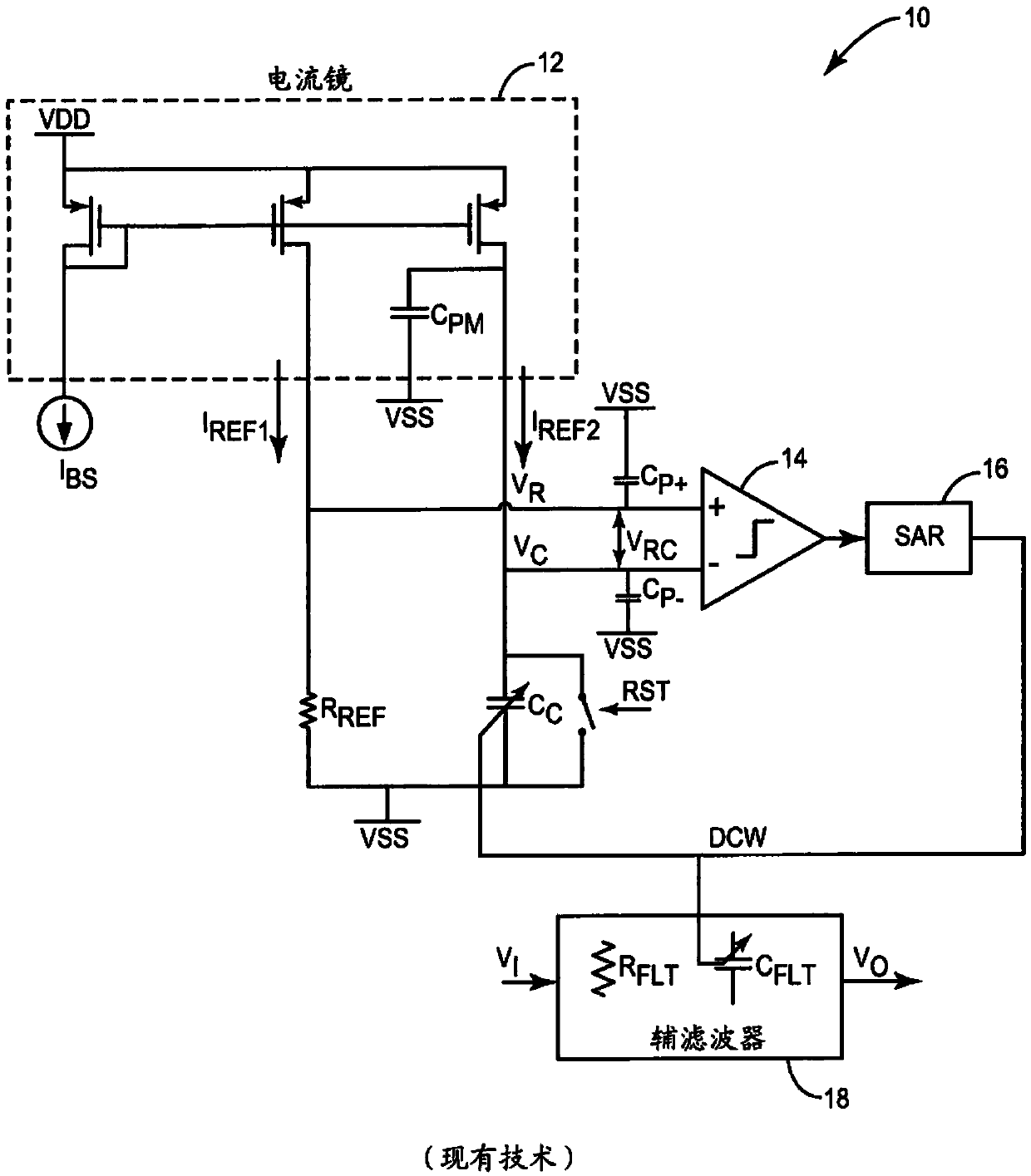
Any extra capacitance added to the output node of the current source will result in an RC time constant calibration error because the charge discharged by the current source will be charged by C C and C PM shared
Therefore, even if the circuit layout size is not limited, the conventional RC time constant calibration circuit 10 (for example, figure 1 The RC calibration circuit shown in 10) also cannot be optimized for high calibration accuracy,
[0008] Another problem with conventional RC calibration circuits 10 is that between the current source transistors and C C Any parasitic capacitance present in the branch between (for example, parasitic capacitance from the comparator input C P ) will cause a calibration error due to the total charge from the current source being divided by C C shared with parasitic capacitance

Method used


Image

  • High accuracy (resistance-capacitance) RC calibration circuit
  • High accuracy (resistance-capacitance) RC calibration circuit
  • High accuracy (resistance-capacitance) RC calibration circuit

Examples


Embodiment Construction

[0025] figure 2 A functional schematic diagram of the RC calibration circuit 20 according to one embodiment of the present invention is depicted. In this embodiment, a current steering structure is implemented to remove current sources matching requirements. Compared with the conventional RC calibration circuit 10, figure 2 The circuit in 20 generates V from the same current source M1 R and V C , so the structure ensures excellent current matching performance.

[0026] During the initial reset phase, the RC calibration circuit 20 precharges the parasitic capacitance to I REF *R REF . This process will cancel out the parasitic capacitance, which eliminates the connection with the parasitic capacitance C at the output of the current source PM and the loading capacitance C from the comparator input P associated loss of precision. This is described more fully in this article.

[0027] Such as figure 2 The illustrated RC calibration circuit 20 according to one embodim...


PUM


Abstract

In an RC calibration circuit, a single reference current is used to generate voltages across both a resistive and capacitive element. The component value of one of the resistive and capacitive element is successively altered until the voltages are substantially equal. Additionally, parasitic capacitances in the circuit are precharged to the resistive element voltage prior to the comparison. The RC calibration circuit eliminates the errors due to current matching and parasitic capacitances in prior art calibration circuits. The circuit includes a comparator and a digital control circuit (DCW) including a successive approximation register (SAR) holding the value of the digital control word used to control the component value of the tunable resistive or capacitive element. The SAR alters the DCW in an iterative, bit-by-bit binary searching pattern in response to the comparator output.

Description

[0001] priority statement [0002] This application claims priority to U.S. Application Serial No. 61 / 515,181, filed with the U.S. Patent Office on August 4, 2011, entitled "High Precision Resistor Capacitor (RC) Proofing Circuits," the disclosure of which is incorporated by reference in its entirety This article. technical field [0003] The present invention relates generally to electronic circuits, and more particularly to improved RC calibration circuits. Background technique [0004] In modern IC design, especially in the field of portable wireless transceivers, a high degree of integration with a minimum of external components is necessary to reduce costs. In current semiconductor processing without costly trimming processes, the component values ​​of raw passive resistive (R) and capacitive (C) devices can vary over a wide range. Temperature changes can also cause the RC value on the chip to change. This wide RC variation enables the design of continuous-time RC f...

Claims


Application Information

Patent Timeline
IPC IPC(8): H03H7/01H03H11/04H03H11/12
CPCH03H2210/046H03H11/1291H03H2210/028H03H11/0472H03H2210/036H03H2210/025H03H7/0153
Inventor 查尔斯·林
Owner ST ERICSSON SA
Learn More