


Quick Research
Generate reliable direction feasibility study reports for your R&D in just a few steps.

Technical Q&A
Discover and master advanced knowledge NOW. Basics, ideas, possibilities, all at once.

Find Solutions
As an expert in R&D theories, this can generate solutions to your technical problems instantly.

Evaluate Feasibility
Analyze your overall solution with one click, know your potential R&D risks in advance.

Monitor Landscape
Get weekly tech updates, stay abreast of the latest tech innovations and key insights.
A kind of led bracket and led device thereof
A technology for LED brackets and LED devices, which is applied to semiconductor devices, electrical components, circuits, etc., can solve problems such as poor bonding force of conductive pins, reduced light output efficiency, LED failure, etc., to overcome poor bonding force, improve reliability, The effect of improving light extraction efficiency
- Summary
- Abstract
- Description
- Claims
- Application Information
AI Technical Summary
Problems solved by technology
Method used
Image


Examples
Embodiment 1
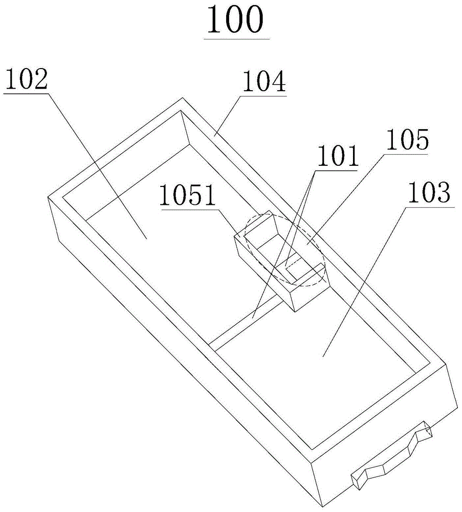
[0044] Such as figure 1 and 2 As shown, this embodiment discloses an LED bracket, including a first pad 102 and a second pad 103 connected together by an insulating bonding glue 101, and the first pad 102 and the second pad 103 are used with the LED chip The two electrodes are electrically connected to play the role of a support and conductive pin. The LED chip is powered by an external power supply through the first pad 102 and the second pad 103. The connection structure between the pad and the external power supply can be the edge of the pad Convex and other conventional structures.
[0045] Such as figure 1 and 2 As shown, the first bonding pad 102 and the second bonding pad 103 form a support bottom plate, and a reflective cup 104 is arranged around the support bottom plate to reflect the LED light emitted by the LED chip after being powered on and improve the light output efficiency of the LED. The shape of the reflective cup includes but is not limited to the shape ...
Embodiment 2
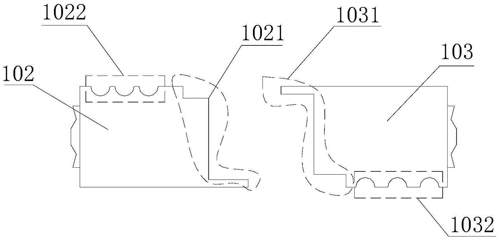
[0056] Such as Figure 4 As shown, the difference between this embodiment and Embodiment 1 is that the shape of the concavo-convex part is different on the second edge 1022 of the first pad 102 and the fourth edge 1032 of the second pad 103, and the convex part is square Or a semicircular protruding part, and the concave part is the gap between the two protruding parts.
[0057] Compared with Example 1, the outward protruding square or quasi-semicircular convex portion of this example not only increases the bonding force between the reflective cup 104 and the metal pads (102, 103), but also increases the heat dissipation of the product area, so the bracket of this embodiment has better heat dissipation.
Embodiment 3
[0059] Such as Figure 5 As shown, the difference between this embodiment and Embodiment 1-2 is only that: a first injection hole 1023 to enhance the bonding force is provided in the area where the inside of the first pad 102 is combined with the bottom of the reflective cup 104, and in the first pad 102 A second injection hole 1033 that strengthens the bonding force is provided in the area where the inside of the second pad 103 is combined with the bottom of the reflector cup 104. The injection hole 1033 in the figure is a quasi-elliptical injection hole, which does not represent a limitation to the shape of the injection hole of the present invention. It is an injection hole of other shapes. The existence of the injection hole increases the bonding area between the metal pad and the plastic when the bracket is injected. At the same time, the existence of this structure makes the height difference between the bottom of the plastic reflection cup 104 and the bottom of the injec...
PUM
 Abstract
Description
Claims
Application Information
 - R&D Engineer
- R&D Manager
- IP Professional
- Industry Leading Data Capabilities
- Powerful AI technology
- Patent DNA Extraction
Browse by: Latest US Patents, China's latest patents, Technical Efficacy Thesaurus, Application Domain, Technology Topic, Popular Technical Reports.
© 2024 PatSnap. All rights reserved.Legal|Privacy policy|Modern Slavery Act Transparency Statement|Sitemap|About US| Contact US: help@patsnap.com