
A Spatial Calibration Body Based on Virtual Ball and Its Calibration Method

A calibration method and virtual ball technology, which are applied to the space calibration body based on the virtual ball and its calibration field, can solve the problems of affecting the accuracy of calibration results, high processing costs, errors, etc.

Active Publication Date: 2016-07-06
HEFEI UNIV OF TECH
View PDF5 Cites 3 Cited by
  • Summary
  • Abstract
  • Description
  • Claims
  • Application Information

AI Technical Summary

Problems solved by technology

At the same time, the higher the accuracy of the standard ball, the higher the processing cost
[0007] 2. When using a high-precision standard sphere, the error introduced by the distribution of sampling points
In a non-constant temperature measurement environment, when using a gauge block with a nominal length of 500mm, when the measurement environment temperature changes by 3-5°C, a systematic error of 20-30μm will be introduced, which will directly affect the accuracy of the calibration results.
[0012] 2. The machining accuracy of the working face is high
In fact, due to the difference in the distribution of sampling points at the end of the reference surface, there will be certain errors in the fitted plane, which will directly affect the working length of the gauge block, and further affect the accuracy of the calibration results of the articulated coordinate measuring machine

Method used


Image

  • A Spatial Calibration Body Based on Virtual Ball and Its Calibration Method
  • A Spatial Calibration Body Based on Virtual Ball and Its Calibration Method
  • A Spatial Calibration Body Based on Virtual Ball and Its Calibration Method

Examples


Embodiment Construction

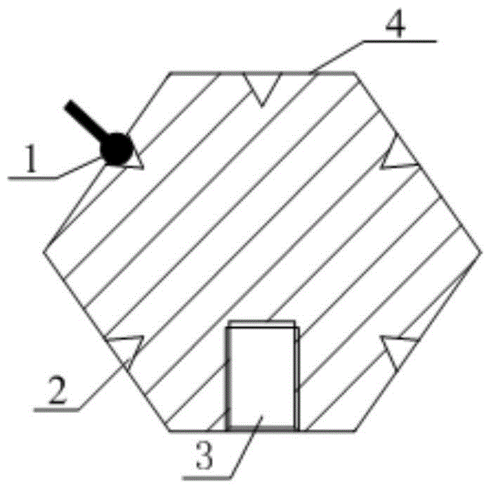
[0042] Referring to the accompanying drawings, a space calibration body based on a virtual sphere and its calibration method, the regular octahedron 4 with the top cut off is selected as the main body of the virtual ball, and a cone socket 2 is processed on each surface, and a surface with a top cut off A taper socket 2 is machined at the center, and an M6×10 threaded hole is machined at the center of the other top surface. During the specific implementation process, the taper angle is set to 60-120°; the purpose of the taper socket 2 is to locate the joint to be marked The probe 1 of the type coordinate measuring machine must ensure that each cone dimple must have a good conicity;

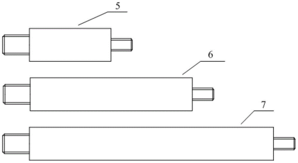
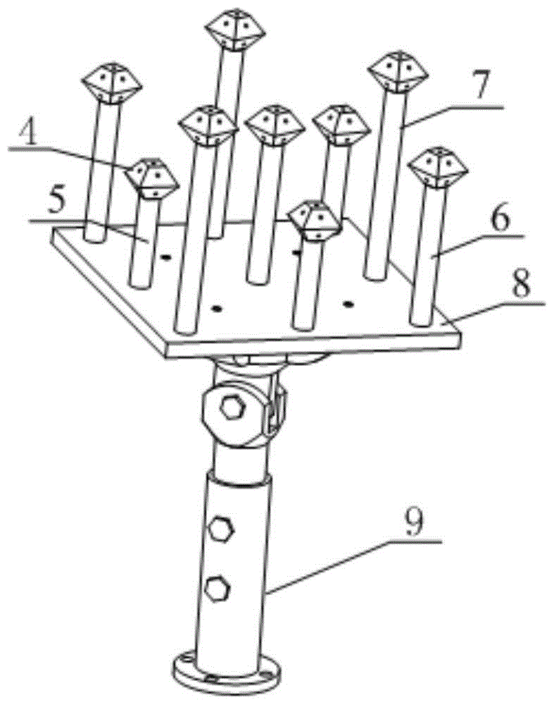
[0043] First, the regular octahedron 4 with the cut top and the standard rods 5, 6, and 7 are fixedly connected with threads respectively, and secondly, refer to image 3 , according to the corresponding positions, the standard rods 5, 6, 7 are fixed to the hard aluminum alloy plate 8 through thre...


PUM


Abstract

The invention discloses a space calibrating body and method based on a virtual ball. According to the space calibrating body and method based on the virtual ball, calibration is conducted in the form that a standard bar piece is separated from a base, a laser tracker is adopted to serve as measurement equipment, and a hard aluminum alloy plate is adopted by the base to serve as an installation platform of the standard bar piece. The space calibrating method based on the virtual ball comprises the steps that the space calibrating body which has three degrees of freedom is manufactured firstly, threads are machined at the two ends of the standard bar piece, one end of the standard bar piece is fixed to the hard aluminum alloy plate, the other end of the standard bar piece is used for fixing the body of the virtual ball, a regular octahedron with the top end cut off serves as the body of the virtual ball, a cone nest is machined on each face of the virtual ball, and then the virtual ball is calibrated with the laser tracker serving as the measurement equipment. The space calibrating body and method based on the virtual ball have the advantages that the precision is high, machining requirements for the standard piece are low, the number of needed sampling points is small when the space calibrating body and method are used, the calibrating efficiency is improved, and the sampling workload is greatly reduced and the calibrating efficiency is improved when an articulated type coordinate measuring machine is calibrated.

Description

technical field [0001] The invention relates to a space calibration body based on a virtual ball and belongs to the technical field of joint coordinate measuring machines, in particular to a space calibration body based on a virtual ball and a calibration method thereof. Background technique [0002] The articulated coordinate measuring machine is usually an open-chain structure formed by each measuring arm connected in series with each rotary joint or linear displacement joint, and its end is the probe of the articulated coordinate measuring machine. Some joints rotate around their own axes, while others translate along their axes. In order to record the variation of joints, each joint that undergoes relative motion can be installed with an angle sensor or a linear displacement sensor. When using an articulated coordinate measuring machine for measurement, its three-dimensional coordinates are a function of the structural parameters of the measuring machine and the relativ...

Claims


Application Information

Patent Timeline
Patent Type & Authority Patents(China)
IPC IPC(8): G01B21/00
Inventor 于连栋赵会宁董钊李维诗郑文兴鲁思颖韩丽玲
Owner HEFEI UNIV OF TECH
Learn More