A belt grinder
A grinding machine and abrasive belt technology, applied in the field of machinery, can solve the problems of uneven grinding, workpiece surface grinding, and inability to maintain consistent grinding accuracy on the surface of the workpiece, and achieve uniform grinding, ensure grinding accuracy, and facilitate adjustment.
- Summary
- Abstract
- Description
- Claims
- Application Information
AI Technical Summary
Problems solved by technology
Method used
Image

Examples
Embodiment 1
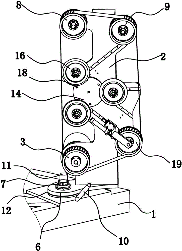
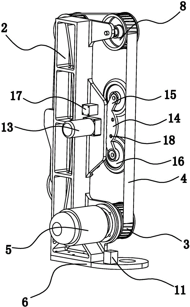
[0038] Such as figure 1 with figure 2Shown, a kind of abrasive belt grinder, comprises the frame 2 that is installed on a base 1, is provided with driving wheel 3, driven wheel one 8, driven wheel two 9, tension pulley 19 and abrasive belt 4 on frame 2 , The abrasive belt 4 is set on the driving wheel 3, the driven wheel one 8, and the driven wheel two 9, and the tension pulley 19 abuts against the inner side of the abrasive belt 4 so that the abrasive belt 4 is in a tensioned state. Driving wheel 3 links with a grinding motor 5, and driven wheel one 8 and driven wheel two 9 are all positioned at the top of driving wheel 3, and driven wheel one 8 is positioned at the top of driving wheel 3. Frame 2 bottom is fixedly connected with connecting plate 6, is provided with the rotating shaft 7 that can make connecting plate 6 rotate with respect to base 1 between connecting plate 6 and base 1, and the abrasive belt 4 between driving wheel 3 and driven wheel-8 and The base 1 is ve...
Embodiment 2
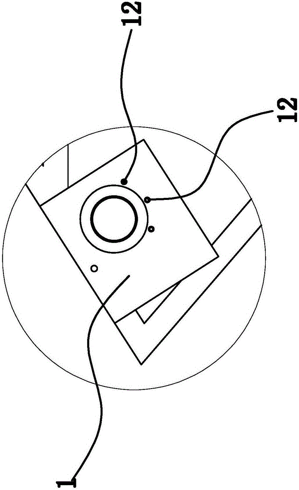
[0049] The structure and principle of this embodiment are basically the same as that of Embodiment 1, the difference is that the positioning structure in this embodiment includes a positioning cylinder 11 fixed in the base 1 and a number of positioning holes 11 arranged at the bottom of the connecting plate 6 12. Each positioning hole 12 is located on the same circle with the rotating shaft 7 as the center, and the piston rod of the positioning cylinder 11 can be inserted into the positioning hole 12. In this embodiment, the matching method between the positioning cylinder one 11 and the positioning hole one 12 is the same as that in the first embodiment.
Embodiment 3
[0051] The structure and principle of this embodiment are basically the same as those in Embodiment 1, except that the positioning structure in this embodiment includes a positioning cylinder 11 fixed on the bottom side of the frame 2 and a number of positioning cylinders arranged on the base 1. Hole one 12, the end of the piston rod of positioning cylinder one 11 is connected with positioning pin, and each positioning hole one 12 is on the same circle with rotating shaft 7 as the center of circle, and connecting plate 6 is provided with and each positioning hole one 12 one-to-one correspondences. The connecting hole, the positioning pin can pass through the connecting hole and be inserted into the positioning hole one 12 . When positioning, the piston rod of the positioning cylinder 11 is ejected downward according to the set procedure, and the positioning pin connected to the end of the piston rod of the positioning cylinder 11 moves downward, and the positioning pin passes t...
PUM
 Abstract
Description
Claims
Application Information
 - R&D
- Intellectual Property
- Life Sciences
- Materials
- Tech Scout
- Unparalleled Data Quality
- Higher Quality Content
- 60% Fewer Hallucinations
Browse by: Latest US Patents, China's latest patents, Technical Efficacy Thesaurus, Application Domain, Technology Topic, Popular Technical Reports.
© 2025 PatSnap. All rights reserved.Legal|Privacy policy|Modern Slavery Act Transparency Statement|Sitemap|About US| Contact US: help@patsnap.com