Energy recycling system and method for liquid hydrogen fuel cell car
What is Al technical title?
Al technical title is built by PatSnap Al team. It summarizes the technical point description of the patent document.
A fuel cell and energy recovery technology, applied in electric vehicles, electric braking systems, vehicle energy storage, etc., can solve the problems of inability to achieve high-efficiency energy recovery, low operating efficiency, and low operating efficiency of DC choppers
Inactive Publication Date: 2014-04-30
UNIV OF ELECTRONICS SCI & TECH OF CHINA
View PDF5 Cites 14 Cited by
Summary
Abstract
Description
Claims
Application Information
AI Technical Summary
This helps you quickly interpret patents by identifying the three key elements:
Problems solved by technology
Method used
Benefits of technology
Problems solved by technology
[0004] The energy absorption and release process of the superconducting magnetic energy storage device needs to be equipped with an additional DC chopper, but the existing traditional DC chopper and full-bridge DC chopper cannot directly and effectively work in liquid hydrogen fuel cells. on the car
The traditional DC chopper consists of two insulated gate bipolar transistors or metal-oxide-semiconductor field effect transistors, and two power diodes, which are suitable for high-voltage applications (such as 500V or above); due to the power diodes Influenced by the inherent conduction voltage drop, the operating efficiency of traditional DC choppers in medium
Method used
Image
Click on the blue label to locate the original text in one second.
Reading with bidirectional positioning of images and text.
Examples
Embodiment 1
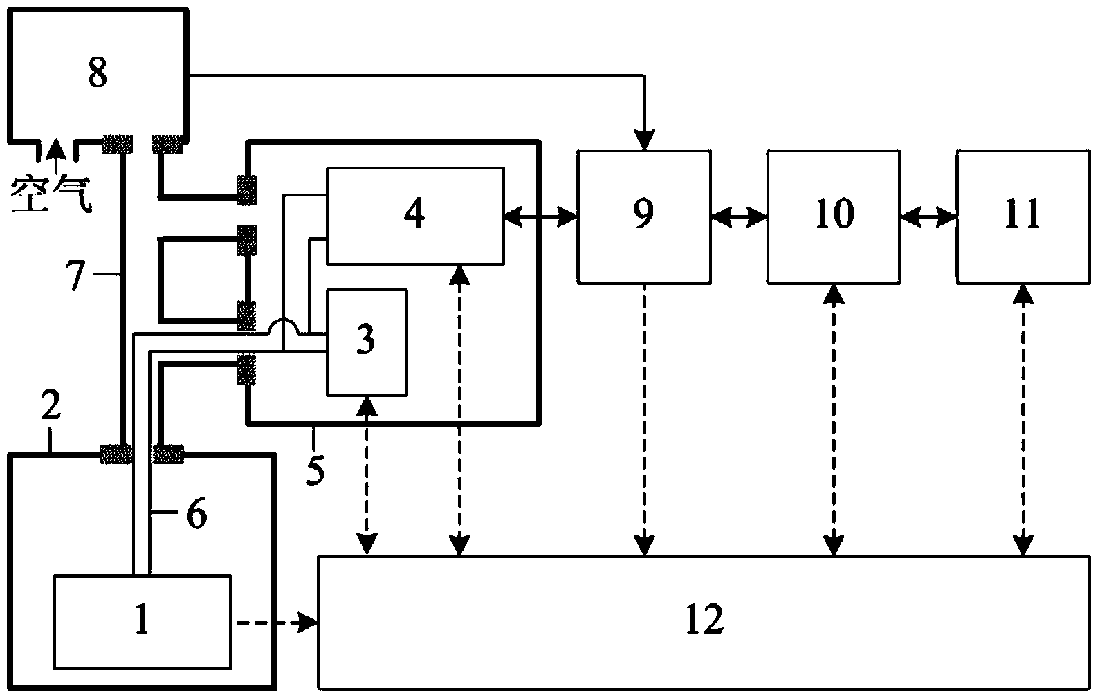
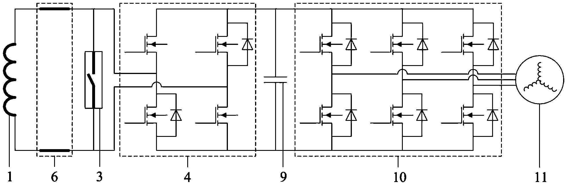
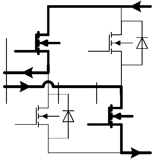
[0048] Such as figure 1 , figure 2 , image 3 , Figure 4 , Figure 5 , Image 6 , Figure 7 , Figure 8 shown. Aiming at an existing liquid hydrogen fuel cell vehicle, the system of the present invention is used to perform energy recovery and utilization operation. The system is connected to a vehicle-mounted liquid hydrogen fuel cell 8, and includes a superconducting coil 1 immersed in a liquid hydrogen container 2, a superconducting switch 3 installed in a low-temperature Dewar 5, a full-bridge DC chopper 4, and a low-temperature hydrogen Pipeline 7 , superconducting current leads 6 arranged in cryogenic hydrogen pipeline 7 , DC link capacitor 9 , DC-AC bidirectional converter 10 , on-board motor 11 and measurement and control system 12 .
[0049]Among them, the superconducting current lead 6 is used to connect the superconducting coil 1, the superconducting switch 3 and the full-bridge DC chopper 4; the superconducting coil 1 is made of BSCCO wire, and its inducta...
Embodiment 2
[0062] Such as figure 1 , figure 2 , image 3 , Figure 4 , Figure 5 , Image 6 , Figure 7 , Figure 8 As shown, the same place as in Embodiment 1 will not be repeated, the difference is that: the superconducting coil 1 is made of YBCO wire; the superconducting current lead 6 is a YBCO wire; the low-temperature hydrogen pipeline 7 is a thermally insulated low-temperature hard tube ; The low-temperature Dewar 5 is an adiabatic low-temperature glass fiber reinforced plastic container; the superconducting switch 3 is a magneto-controlled superconducting switch.
Embodiment 3
[0064] Such as figure 1 , figure 2 , image 3 , Figure 4 , Figure 5 , Image 6 , Figure 7 , Figure 8 As shown, the same place as in Embodiment 1 will not be repeated, the difference is that the superconducting coil 1 is made of MgB 2 The wire is wound; the superconducting current lead 6 is MgB 2 wire; the superconducting switch 3 is a heat-controlled superconducting switch.
PUM
Abstract
The invention discloses an energy recycling system and method for a liquid hydrogen fuel cell car. The system comprises a superconducting coil, a superconducting switch, a full-bridge type direct current chopper, a superconducting current lead, a direct current link capacitor, a DC-AC bilateral transducer, a vehicle-mounted motor and a measurement and control system, wherein the superconducting coil is immersed in a liquid hydrogen container, the superconducting switch and the full-bridge type direct current chopper are installed in a low-temperature Duval, and the superconducting current lead, the direct current link capacitor, the DC-AC bilateral transducer, the vehicle-mounted motor and the measurement and control system are arranged in a low-temperature hydrogen pipeline. The superconducting current lead is used for connecting the superconducting coil, the superconducting switch and the full-bridge type direct current chopper. The low-temperature hydrogen pipeline is used for connecting a liquid hydrogen fuel cell, the liquid hydrogen container and the low-temperature Duval. Compared with the prior art, the energy recycling system has the advantages that the superconducting coil is cooled directly through vehicle-mounted liquid hydrogen, the superconducting current lead, the superconducting switch and the full-bridge type direct current chopper are cooled directly through the low-temperature hydrogen produced through gasification of the vehicle-mounted liquid hydrogen, a supermumetal energy storing device is actually used in the liquid hydrogen fuel cell car, the brake energy recycling and reutilizing ratio of the car is improved, and staring time and accelerating time of the car are shortened.
Description
technical field [0001] The invention belongs to the technical field of energy recovery and recycling, and in particular relates to a system and method for efficient energy recovery and reuse of liquid hydrogen fuel cell vehicles. Background technique [0002] With the increasing consumption of oil resources, the automobile industry is facing two major problems, the shortage of oil resources and the aggravation of environmental pollution. In recent years, new energy vehicles have become a new direction of automobile development and are expected to become the mainstream direction in the future; among them, fuel cell vehicles using high-pressure hydrogen or low-temperature liquid hydrogen as fuel are gradually being introduced to the market. In order to improve vehicle energy utilization efficiency, current fuel cell vehicles are often equipped with battery devices to recover vehicle braking energy; however, the repeated charging and discharging times and service life of the ba...
Claims
Application Information
Patent Timeline
Application Date:The date an application was filed.
Publication Date:The date a patent or application was officially published.
First Publication Date:The earliest publication date of a patent with the same application number.
Issue Date:Publication date of the patent grant document.
PCT Entry Date:The Entry date of PCT National Phase.
Estimated Expiry Date:The statutory expiry date of a patent right according to the Patent Law, and it is the longest term of protection that the patent right can achieve without the termination of the patent right due to other reasons(Term extension factor has been taken into account ).
Invalid Date:Actual expiry date is based on effective date or publication date of legal transaction data of invalid patent.