
Reflector for light-emitting diode and housing

A technology of light-emitting diodes and reflectors, which is applied in the field of reflectors, can solve the problems that fluororesin cannot be used and the reflectivity is reduced, and achieve the effect of high reflectivity and excellent heat resistance

Inactive Publication Date: 2014-04-02
DUPONT MITSUI FLUOROCHEMICALS CO LTD
View PDF3 Cites 0 Cited by
  • Summary
  • Abstract
  • Description
  • Claims
  • Application Information

AI Technical Summary

Problems solved by technology

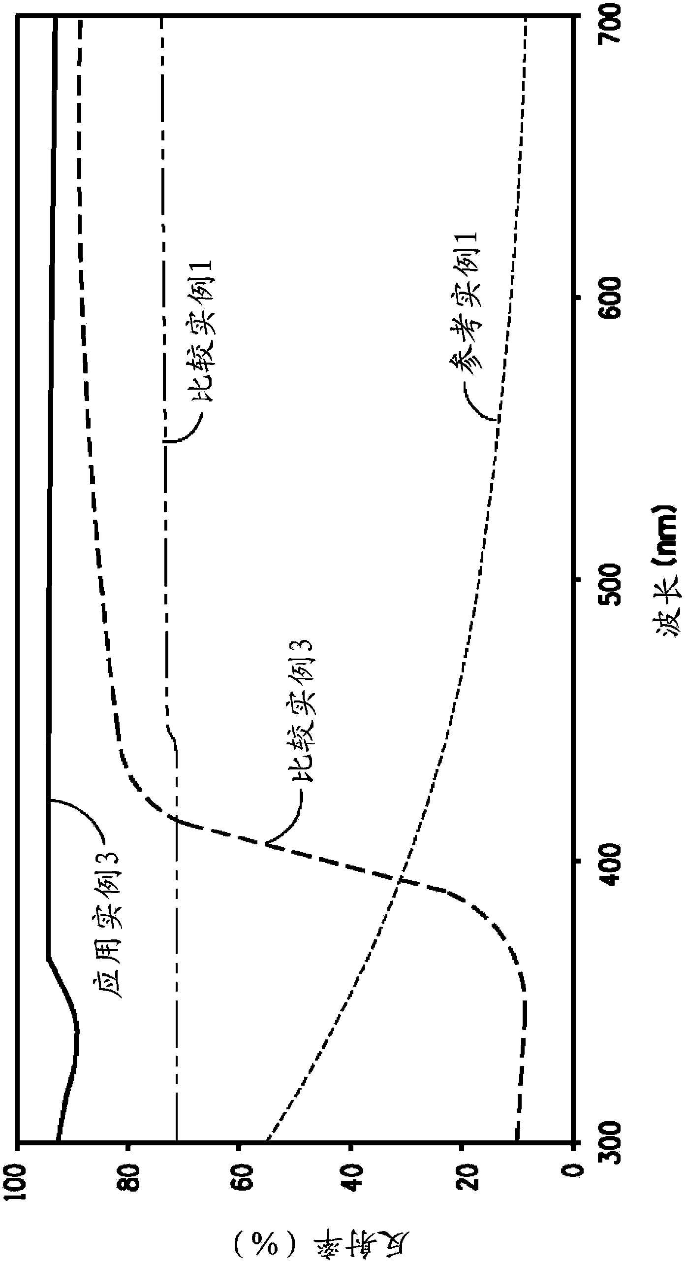
However, like the aforementioned polyamide-based resin (Comparative Example 3 of the present application), since titanium dioxide for absorbing ultraviolet rays is used as a filler, the reflectance in the ultraviolet region is greatly reduced (see Comparative Example 2 of the present application), and The fluororesin cannot be used in reflectors for ultraviolet LEDs, and cannot be used in reflectors for white LEDs in which ultraviolet LEDs are combined with fluorescent materials having three colors of red, green and blue

Method used

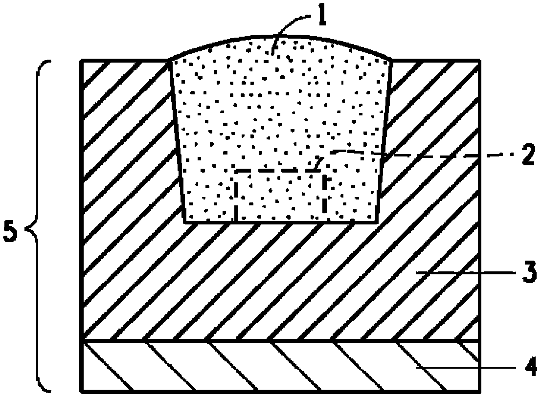
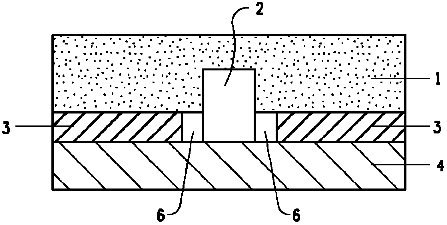

Image

  • Reflector for light-emitting diode and housing
  • Reflector for light-emitting diode and housing
  • Reflector for light-emitting diode and housing

Examples


example

[0058] Next, the present invention will be explained in more detail through application examples and comparative examples. However, the present invention is not limited by this explanation.

[0059] Each property in the present invention is measured by the following method.

[0060] A. Measurement of performance

[0061] (1) Melting point (melting peak temperature)

[0062] A differential scanning calorimeter (Pyris1 type DSC, manufactured by Perkin Elmer Co.) was used. Weigh about 10 mg of the sample, put it into a special aluminum pan, fold it with a special crimper, and put it in the DSC main body, and raise the temperature from 150°C to 360°C at 10°C / min. At that time, the melting peak temperature (Tm) was obtained from the obtained melting curve.

[0063] (2) Melt flow rate (MFR)

[0064] Using a melt indexer (manufactured by Toyo Seiki Co., Ltd.) for corrosion-resistant drums, molds, and pistons, based on ASTM D-1238-95, 5 g of sample powder was filled into a ...


PUM

PropertyMeasurementUnit
particle sizeaaaaaaaaaa

Abstract

Provided is a reflector for a light-emitting diode which has a small decrease in reflectance in a range from the ultraviolet region to visible region, and has excellent heat resistance, light resistance, and weather resistance, and a housing having this reflector. The reflector for a light-emitting diode is obtained by molding a fluororesin composition containing a filler with an average particle diameter of smaller than 1 [mu]m, wherein the difference between the maximum value and the minimum value of the reflectance at a wavelength of 240-700 nm is within 25%.

Description

technical field [0001] The present invention relates to reflectors for light emitting diodes (alternatively referred to herein as LEDs) having high reflectivity and a small decrease in reflectivity in the ultraviolet to visible range. The reflector has excellent heat resistance, light resistance and weather resistance. The invention also relates to a housing for a light-emitting diode having said reflector. Background technique [0002] Recently, light emitting diode elements (alternatively referred to herein as LED chips) are small in size and capable of lighting for a long time compared to filament light bulbs. Because of their high power-to-light conversion efficiency, there is a strong tendency for these elements to replace conventional luminaires including straight tube type fluorescent lamps, and these diode elements are widely used as electric home appliances, LED displays, and illuminated type operation switches. The use of LED is divided into general (visible ligh...

Claims


Application Information

Patent Timeline
Patent Type & Authority Applications(China)
IPC IPC(8): H01L33/60C08F214/26
CPCB29K2027/12H01L33/60B29K2995/003B29K2105/06F21V7/22B29C43/003H01L2924/0002F21V7/28F21V7/26H01L2924/00
Inventor P.H.纳姆
Owner DUPONT MITSUI FLUOROCHEMICALS CO LTD
Learn More