
A sncr and scr mixed denitrification system

An SCR reactor and denitrification technology, which is applied in the field of SNCR and SCR mixed denitrification systems, can solve the problems of unsatisfactory denitrification effect, waste of reducing agent, ammonia gas escape, etc., and achieve small footprint, increase in the number of droplets, and reduce Effect of ammonia slip

Inactive Publication Date: 2016-08-17
广东清华中邦热能科技有限公司
View PDF5 Cites 4 Cited by
  • Summary
  • Abstract
  • Description
  • Claims
  • Application Information

AI Technical Summary

Problems solved by technology

[0010] Existing SNCR and SCR denitrification systems generally need to use a pyrolysis device to pyrolyze urea or ammonia water into ammonia gas as a reducing agent. The ammonia gas is sprayed into the boiler or boiler flue through the injection module, which is prone to hidden dangers of ammonia gas escape, and it is common The optimal amount of reductant injection is not automatically and more accurately controlled, which does not correspond to the amount required for real-time denitrification reaction, resulting in excessive reductant causing waste, or too little denitrification effect is not very ideal. Usually, the SNCR denitrification of large boilers The denitrification efficiency of the system is below 40%

Method used


Image

  • A sncr and scr mixed denitrification system
  • A sncr and scr mixed denitrification system
  • A sncr and scr mixed denitrification system

Examples


Embodiment Construction

[0036] The specific embodiment of the present invention will be further described below in conjunction with accompanying drawing:

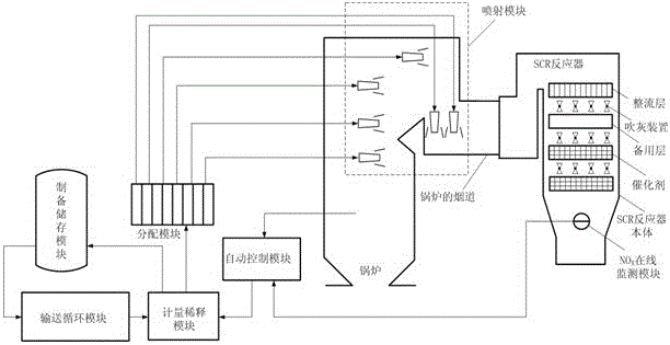
[0037] Such as figure 1 As shown, a SNCR and SCR hybrid denitrification system includes a preparation storage module, a delivery circulation module, a metering dilution module, and NO X Online monitoring module, automatic control module, distribution module, injection module, boiler, SCR reactor.

[0038] The preparation and storage module, the conveying cycle module, and the metering and dilution module are connected in sequence through pipelines, and the metering and dilution module, distribution module, and injection module are connected in sequence through pipelines. The automatic control module is connected to the temperature, pressure and other signals from the boiler through the circuit, and obtained through the circuit. from NO X Monitor the signal of the module online, and output the control signal to the metering dilution module throug...


PUM


Abstract

The invention relates to the technical field of industrial smoke nitric oxide emission reduction and denitrification and relates to a novel SNCR (selective non-catalytic reduction) and SCR (selective catalytic reduction) hybrid denitrification system. The novel SNCR and SCR hybrid denitrification system comprises a preparation and storage module, a conveying circulating module, a metering and diluting module, an on-line NOX monitoring module, an automatic control module, a distribution module, a spraying module, a boiler and an SCR reactor. According to the novel SNCR and SCR hybrid denitrification system, an existing SNCR and SCR denitrification system is improved and united, so that full-automatic intelligent operation is realized; the automatic control module can accurately calculate a demand of a denitrification reducing agent by monitoring a nitride generation amount and other data in smoke gas on line and in real time according to the real-time change of a load of the boiler and feed back information to the metering and diluting module; the metering and diluting module can quickly adjust corresponding equipment to accurately provide the corresponding amount of the reducing agent to the distribution module and the spraying module; the reducing agent and smoke gas are sprayed in the boiler and a flue and are then mixed to enter the SCR reactor to implement denitrification reaction; therefore, the beneficial effects of high denitrification efficiency, high automation degree, low investment cost and good denitrification effect are achieved.

Description

technical field [0001] The invention relates to the technical field of flue gas nitrogen oxide emission reduction and denitrification, and relates to a mixed denitrification system of SNCR and SCR. Background technique [0002] With nitrogen oxides NO X Emissions continue to increase, acid rain pollution has changed from sulfuric acid type to sulfuric acid and nitric acid compound type, and the urban atmospheric environment is still grim. With the development of my country's economy and the improvement of environmental standards, flue gas denitrification technology will be widely used in my country's thermal power, domestic waste incineration and cement industries. At present, the mainstream flue gas denitrification technologies mainly include selective catalytic reduction (SCR), selective non-catalytic reduction (SNCR), and low-nitrogen combustion technology. Among them, SCR technology is the most efficient, most widely used and most mature denitrification technology. ...

Claims


Application Information

Patent Timeline
Patent Type & Authority Patents(China)
IPC IPC(8): B01D53/79B01D53/86B01D53/56B01D53/30
CPCY02C20/10
Inventor 林卓晖
Owner 广东清华中邦热能科技有限公司
Learn More