
Distributed optical fiber temperature strain sensor based on Brillouin optical amplification detection

A distributed optical fiber and temperature strain technology, applied in the direction of instruments, measuring devices, etc., can solve problems such as difficulty in obtaining flat frequency response characteristics, and achieve the effects of precision detection, flat frequency response characteristics, and reduction of technical difficulty and cost

Active Publication Date: 2014-03-26
BEIJING AEROSPACE TIMES OPTICAL ELECTRONICS TECH
View PDF7 Cites 24 Cited by
  • Summary
  • Abstract
  • Description
  • Claims
  • Application Information

AI Technical Summary

Problems solved by technology

[0006] The purpose of the present invention is to overcome the existing distributed optical fiber temperature strain sensor of the Brillouin optical time domain reflectometer scheme based on optical heterodyne coherent detection, microwave frequency conversion and electric signal spectrum detection, which needs to adopt high-cost microwave devices and is difficult The problem of obtaining flat frequency response characteristics, a distributed fiber optic temperature strain sensor based on Brillouin optical amplification detection is proposed

Method used


Image

  • Distributed optical fiber temperature strain sensor based on Brillouin optical amplification detection
  • Distributed optical fiber temperature strain sensor based on Brillouin optical amplification detection
  • Distributed optical fiber temperature strain sensor based on Brillouin optical amplification detection

Examples


Embodiment

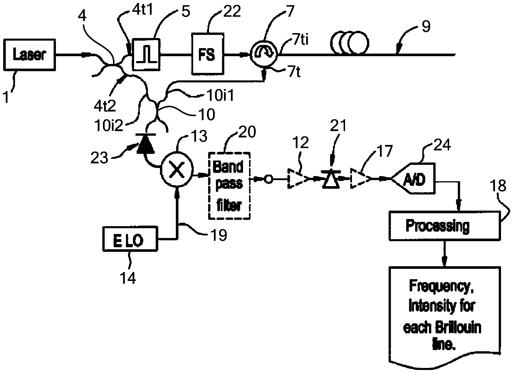
[0057] Such as image 3 As shown, a distributed optical fiber temperature strain sensor based on Brillouin optical amplification detection, including a light source 1, a fiber coupler 4, an optical pulse modulation unit 5, a first optical amplifier 6, a first optical circulator 7, a sensor Optical fiber 9, optical frequency shift unit 22, second optical amplifier 25, polarization controller 28, optical power control unit 29, second optical circulator 27, Brillouin gain fiber 26, narrow linewidth optical filter 30, photoelectric detection Device 23, analog-to-digital converter 24 and signal processing unit 18;

[0058] The output of the light source 1 is connected to the input port 4i of the fiber coupler 4, the first output port 4t1 of the fiber coupler 4 is connected to the input port of the optical pulse modulation unit 5, and the output port of the optical pulse modulation unit 5 is connected to the input of the first optical amplifier 6 port, the output port of the first ...


PUM

PropertyMeasurementUnit
Line widthaaaaaaaaaa

Abstract

The invention relates to a distributed optical fiber temperature strain sensor based on Brillouin optical amplification detection. The narrow-band Brillouin gain feature of a Brillouin gain optical fiber is used to detect the frequency shift of the Brillouin scattering light of a sensing optical fiber. The Brillouin scattering light and the frequency shift light input the Brillouin gain optical fiber from two ends. A narrow linewidth optical filter filters the stokes or anti-stokes sidebands of the Brillouin scattering light to perform photoelectric detection. An optical power control unit stably controls the power of the frequency shift light. When the frequency difference between the Brillouin scattering light and the frequency shift light equals to the Brillouin frequency shift of the Brillouin gain optical fiber, the strongest photoelectric detection signal is obtained, and detection of the Brillouin scattering light is achieved. The distributed optical fiber temperature strain sensor has the advantages that the frequency of photoelectric detection, circuit signal production and processing is lowered, technical difficulty and cost are lowered, flat frequency response feature is obtained by stable control of the frequency shift power, and precise detection of Brillouin scattering light frequency shift is facilitated.

Description

technical field [0001] The invention relates to a distributed optical fiber temperature strain sensor, in particular to a distributed optical fiber temperature strain sensor based on Brillouin light amplification detection, which belongs to the technical field of optical fiber sensors. Background technique [0002] There is a good linearity between the frequency shift of the Brillouin scattered light generated when light propagates in the fiber and the temperature and strain of the fiber. The frequency shift-temperature sensitivity is about 1.05MHz / ℃, and the frequency shift-strain sensitivity is about 0.046MHz. / με; by measuring the frequency shift of the Brillouin scattered light generated when the optical pulse propagates in the optical fiber, and at the same time using the optical pulse propagation delay to achieve positioning, the temperature and strain information continuously distributed along the optical fiber can be obtained, that is, the distributed optical fiber te...

Claims


Application Information

Patent Timeline
IPC IPC(8): G01D21/02
Inventor 唐才杰王巍王学锋崔留住
Owner BEIJING AEROSPACE TIMES OPTICAL ELECTRONICS TECH
Learn More