Spring grinding machine
What is Al technical title?
Al technical title is built by PatSnap Al team. It summarizes the technical point description of the patent document.
A technology of spring grinding machine and motor pump, which is applied in the field of grinding spring machinery and spring grinding machine, which can solve the problems of damage to parts, increase the space occupation of the production site, and have a good cooling effect, so as to prevent damage to parts and reduce the size of the machine. The effect of equipment occupying space and avoiding stability degradation
Inactive Publication Date: 2014-12-24
ZHUJI GUANGXIN AUTOMATION EQUIP
View PDF4 Cites 2 Cited by
Summary
Abstract
Description
Claims
Application Information
AI Technical Summary
This helps you quickly interpret patents by identifying the three key elements:
Problems solved by technology
Method used
Benefits of technology
Problems solved by technology
[0003] In the prior art, the supporting liquid cooling system, hydraulic system and grinding device on the spring grinding machine are all separately placed on the production site, which creates a certain distance between the liquid cooling system, hydraulic system and grinding device, resulting in The liquid cooling system and the hydraulic system need more connecting pipes and spring grinders to connect the cooling equipment and hydraulic equipment, which increases the space occupation of the production site and also increases the investment cost, because the liquid cooling system, hydraulic system and grinding device are all If it is exposed on the production site, without taking protective measures, it is vulnerable to dust and other substances, resulting in unstable operation of the equipment
[0004] In the process of grinding the spring, the temperature of the grinding surface of the spring will continue to rise, which will cause the grinding surface of the spring to be burned and the spring to soften. In order to reduce the temperature of the spring during the grinding process, liquid is used in the prior art The method of circulating cooling is used to reduce the temperature, but the abrasive debris generated by the spring during the grinding process will also flow into the coolant storage tank with the coolant, causing the abrasive debris to accumulate in the coolant storage tank. Since the coolant storage tank is sealed, It is very difficult to remove the grinding debris, and at the same time, the circulating cooling device will also inhale a large amount of grinding debris during operation, causing blockage of the circulating cooling device and damage to parts
[0005] In order to reduce the temperature of the spring during the grinding process, liquid circulation is generally used for cooling. Due to the spring grinding process in the prior art, one is that the spring fixing seat remains in the original position, and the grinding machine moves forward for grinding. The spring fixed seat moves forward, and the grinding machine keeps the original position for grinding. In these two methods, the end face and the grinding wheel of the spring grinding are kept in the grinding state during the whole grinding process from the spring grinding to the predetermined grinding length of the spring. There is no cooling time, especially for springs made of spring steel with a larger diameter, it takes longer in the grinding process, and the temperature of the grinding surface will be higher, so that the temperature of the spring will continue to rise during the grinding process, a single The use of liquid circulation cooling can not achieve a good cooling effect
Method used
Image
Click on the blue label to locate the original text in one second.
Reading with bidirectional positioning of images and text.
Examples
Embodiment Construction
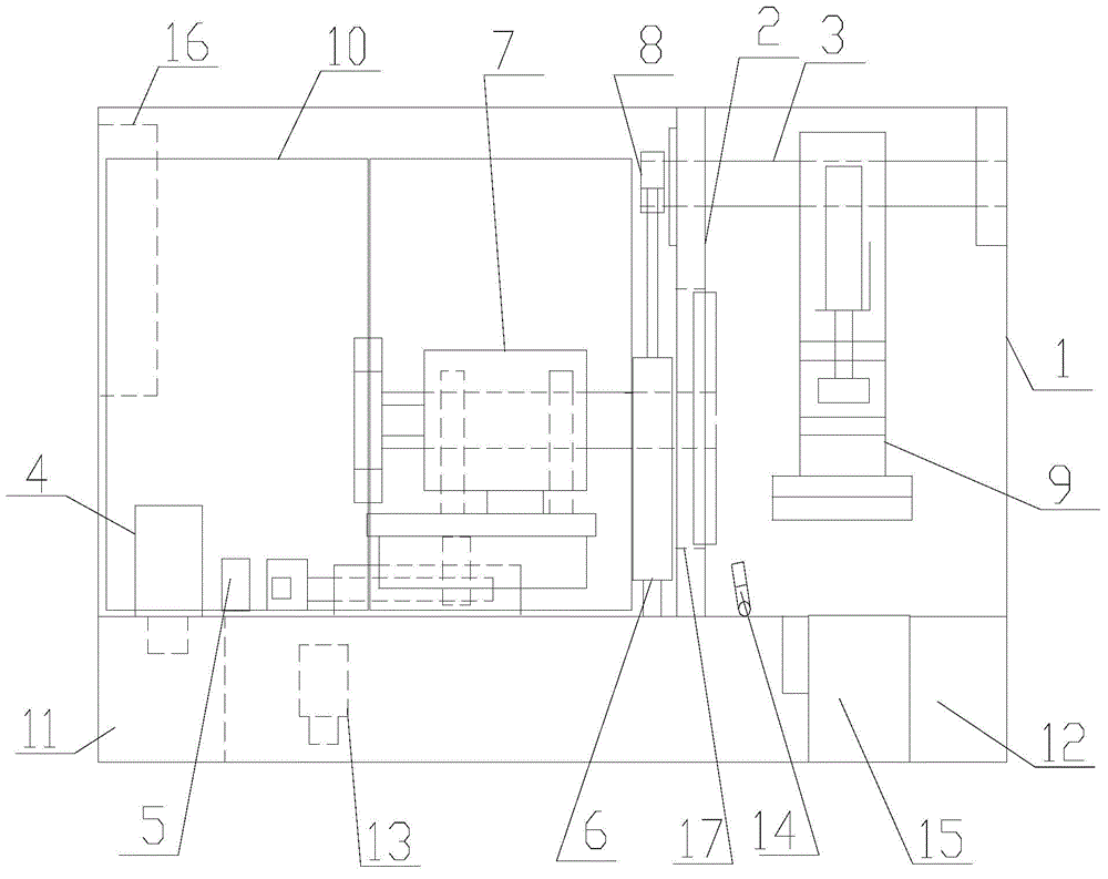
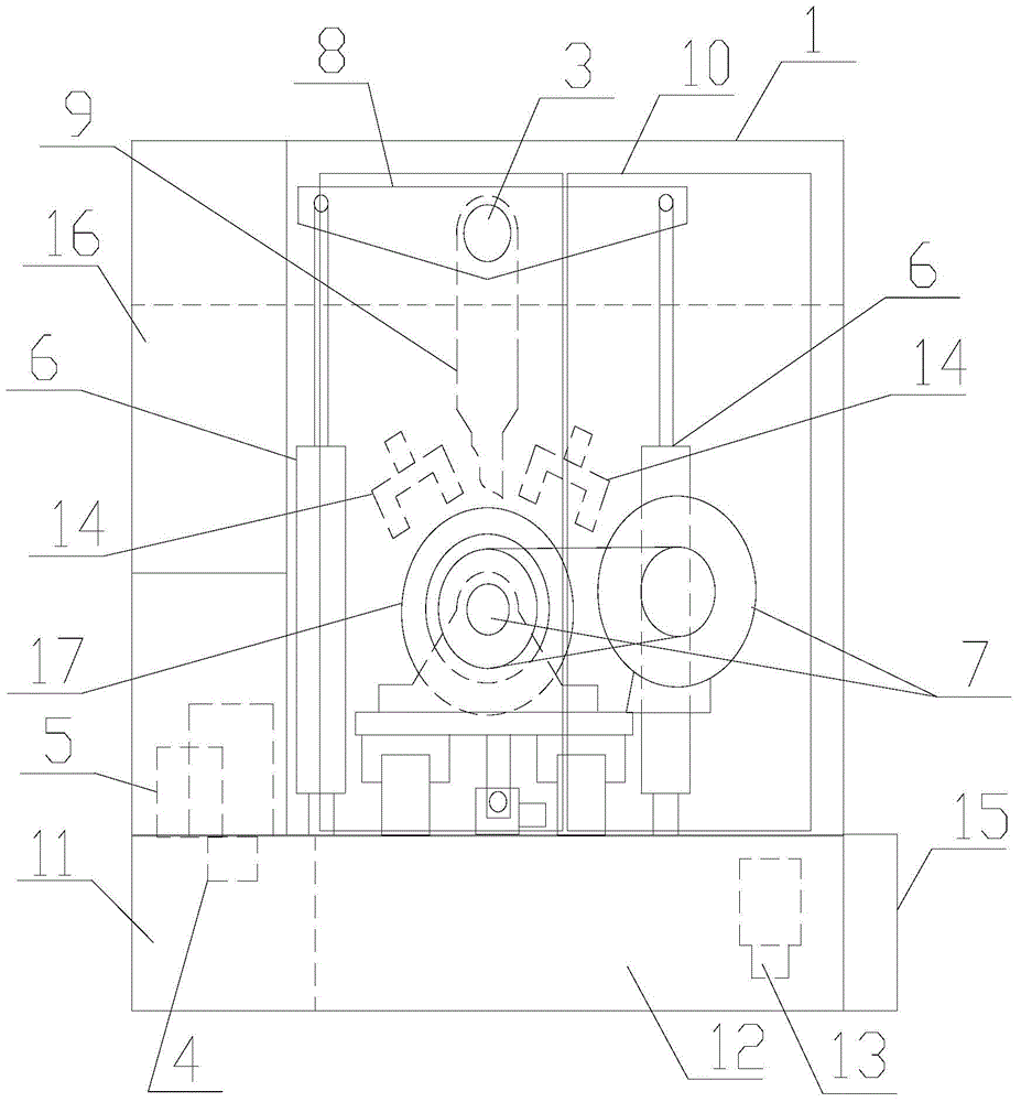
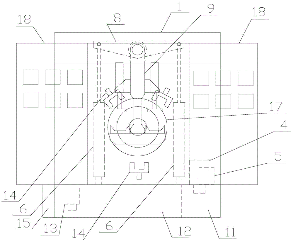
[0030] refer to figure 1 , figure 2 , image 3 , Figure 4 , Figure 5 and Figure 6 , a spring grinding machine of the present invention, comprising a first frame body 1, a partition plate 2, a connecting shaft 3, a first motor pump group 4, a valve group 5, a first hydraulic cylinder 6, a grinder device 7, a connecting arm 8, Support seat 9, protective door 10, oil tank 11, water tank 12, second motor pump group 13, water spray port 14, wear debris separation device 15, electrical box 16 and through hole 17, the input of the first motor pump group 4 The output end of the first motor pump group 4 is connected to the input end of the valve group 5, the output end of the valve group 5 is connected to the first hydraulic cylinder 6, and the input end of the second motor pump group 13 connected to the water tank 12, the output end of the second motor pump unit 13 is connected to the water spray port 14, the first frame body 1 is supported on the oil tank 11 and the water ta...
PUM
Abstract
The invention discloses a spring grinding machine. The spring grinding machine comprises a first frame body, a partition board, a connecting shaft, a first motor pump set, a valve set, a first hydraulic cylinder, a grinding machine device, a connecting arm, a support base, a protection door, an oil tank, a water tank, a second motor pump set, a water injection nozzle, an abrasive dust separating device, an electric appliance cabinet and a through hole, wherein the input end of the first motor pump set is connected with the oil tank, the output end of the first motor pump set is connected with the input end of the valve set, the output end of the valve set is connected to the first hydraulic cylinder, the input end of the second motor pump is connected with the water tank, the output end of the second motor pump set is connected with the water injection nozzle, the first frame body is supported by the oil tank and the water tank, the abrasive dust separating device is arranged on the side face of the water tank, the partition board, the grinding machine device and the water injection nozzle are arranged inside the first frame body, the partition board is provided with the connecting shaft, the through hole and the water injection nozzle, the connecting arm and the support base are arranged on the connecting shaft, a piston rod of the first hydraulic cylinder is connected with the connecting arm in a rotary mode, and the protection door and the electric appliance cabinet are arranged on the first frame body.
Description
【Technical field】 [0001] The invention relates to the technical field of spring grinding machines, in particular to the technical field of spring grinding machines. 【Background technique】 [0002] Generally, due to the shape of the spring, the two ends of the spring will be slightly raised and there will be more uneven material. However, some spring applications require the two ends of the spring to be relatively flat, so that the two ends of the spring and The contact area between the placement surfaces increases, thereby promoting the stability of the positioning, that is, the so-called straight angle of the end face needs to be relatively flat, so a spring grinder must be used to grind and smooth both ends of the spring. [0003] In the prior art, the supporting liquid cooling system, hydraulic system and grinding device on the spring grinding machine are all separately placed on the production site, which creates a certain distance between the liquid cooling system, hydr...
Claims
Application Information
Patent Timeline
Application Date:The date an application was filed.
Publication Date:The date a patent or application was officially published.
First Publication Date:The earliest publication date of a patent with the same application number.
Issue Date:Publication date of the patent grant document.
PCT Entry Date:The Entry date of PCT National Phase.
Estimated Expiry Date:The statutory expiry date of a patent right according to the Patent Law, and it is the longest term of protection that the patent right can achieve without the termination of the patent right due to other reasons(Term extension factor has been taken into account ).
Invalid Date:Actual expiry date is based on effective date or publication date of legal transaction data of invalid patent.