
High sensitivity photoionization detector

A photoionization, high-sensitivity technology, used in instruments, measuring devices, scientific instruments, etc., can solve the problem of not taking into account the electromagnetic interference of the light source driving circuit, the collector or the emitter is not protected, and the detection limit of the detector is weakened. problems, to avoid the photoelectric effect, reduce the cell volume, and achieve the effect of low noise level

Active Publication Date: 2014-02-12
AEROSPACE INFORMATION RES INST CAS +1
View PDF3 Cites 6 Cited by
  • Summary
  • Abstract
  • Description
  • Claims
  • Application Information

AI Technical Summary

Problems solved by technology

[0003] In existing photoionization detectors, the pool volume of the ionization chamber is relatively large, generally greater than 40 microliters, and in almost all designs, the collector or emitter is not protected and exposed to direct ultraviolet light Under the circumstances, since the ionization potential of almost all metals is less than 6eV, photoelectric effect will inevitably occur, and the noise caused by photoelectric effect can reach dozens of pA, which greatly weakens the detection limit of the detector.
In addition, in these designs, the electromagnetic interference brought by the light source driving circuit is hardly considered. The noise caused by this electromagnetic interference can reach dozens of pA noise, which also greatly weakens the detection limit of the detector.

Method used


Image

  • High sensitivity photoionization detector
  • High sensitivity photoionization detector
  • High sensitivity photoionization detector

Examples


Embodiment Construction

[0012] In order to make the object, technical solution and advantages of the present invention clearer, the present invention will be described in further detail below in conjunction with specific embodiments and with reference to the accompanying drawings.

[0013] In order to make the object, technical solution and advantages of the present invention clearer, the present invention will be further described in detail below in conjunction with specific embodiments and with reference to the accompanying drawings.

[0014] Generally speaking, there are many factors that affect the sensitivity of the photoionization detector, mainly including the structure of the ionization chamber and the volume of the cell, the photoelectric effect generated by the direct irradiation of the PID light source on the electrode, and various electromagnetic noises (especially the driving circuit of the PID light source). interference. Therefore, the present invention will aim at improving the sensit...


PUM

PropertyMeasurementUnit
thicknessaaaaaaaaaa
thicknessaaaaaaaaaa

Abstract

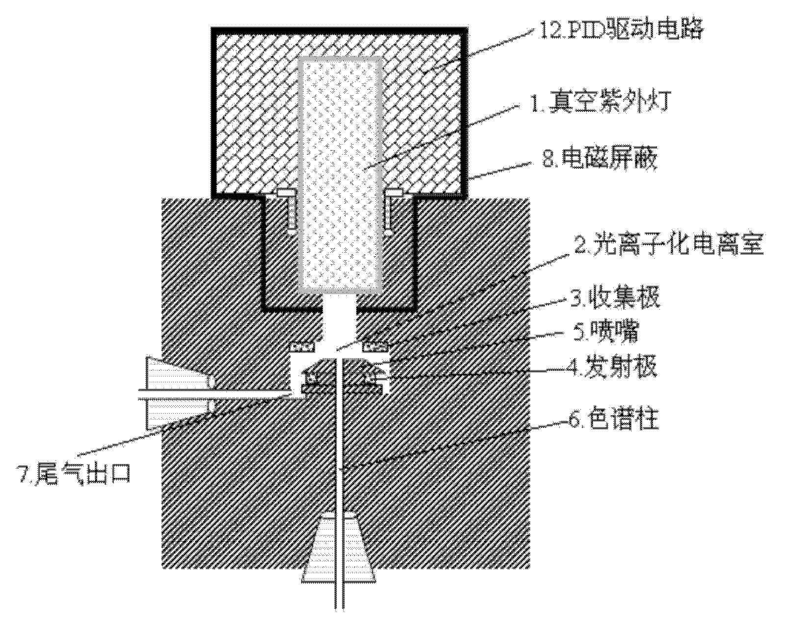
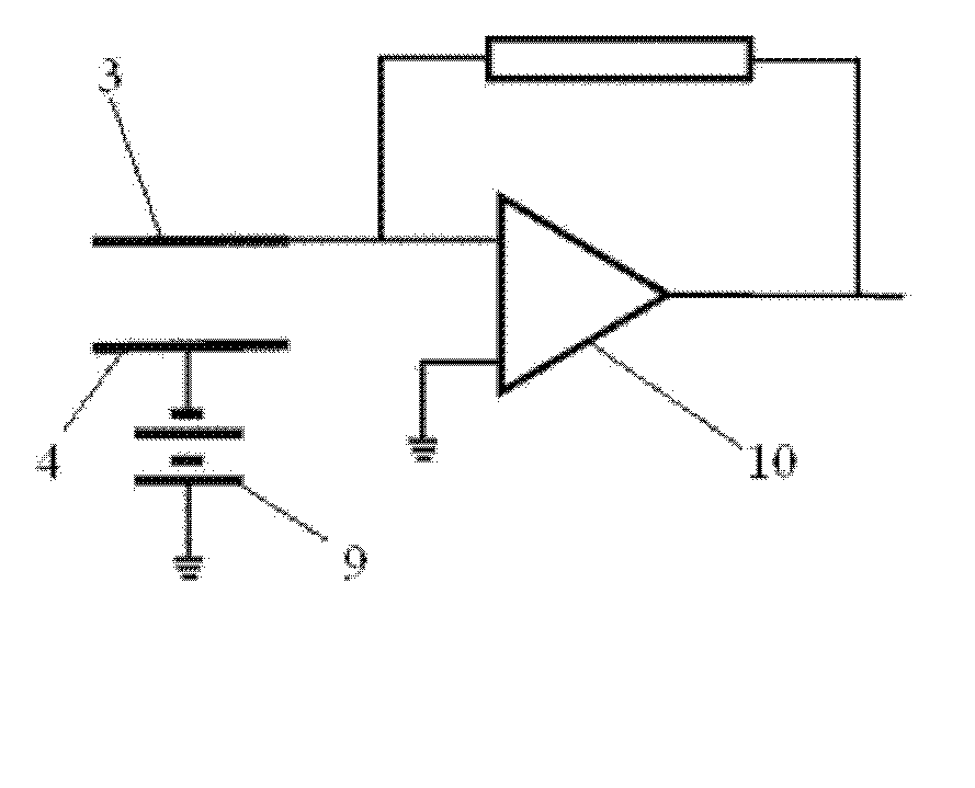
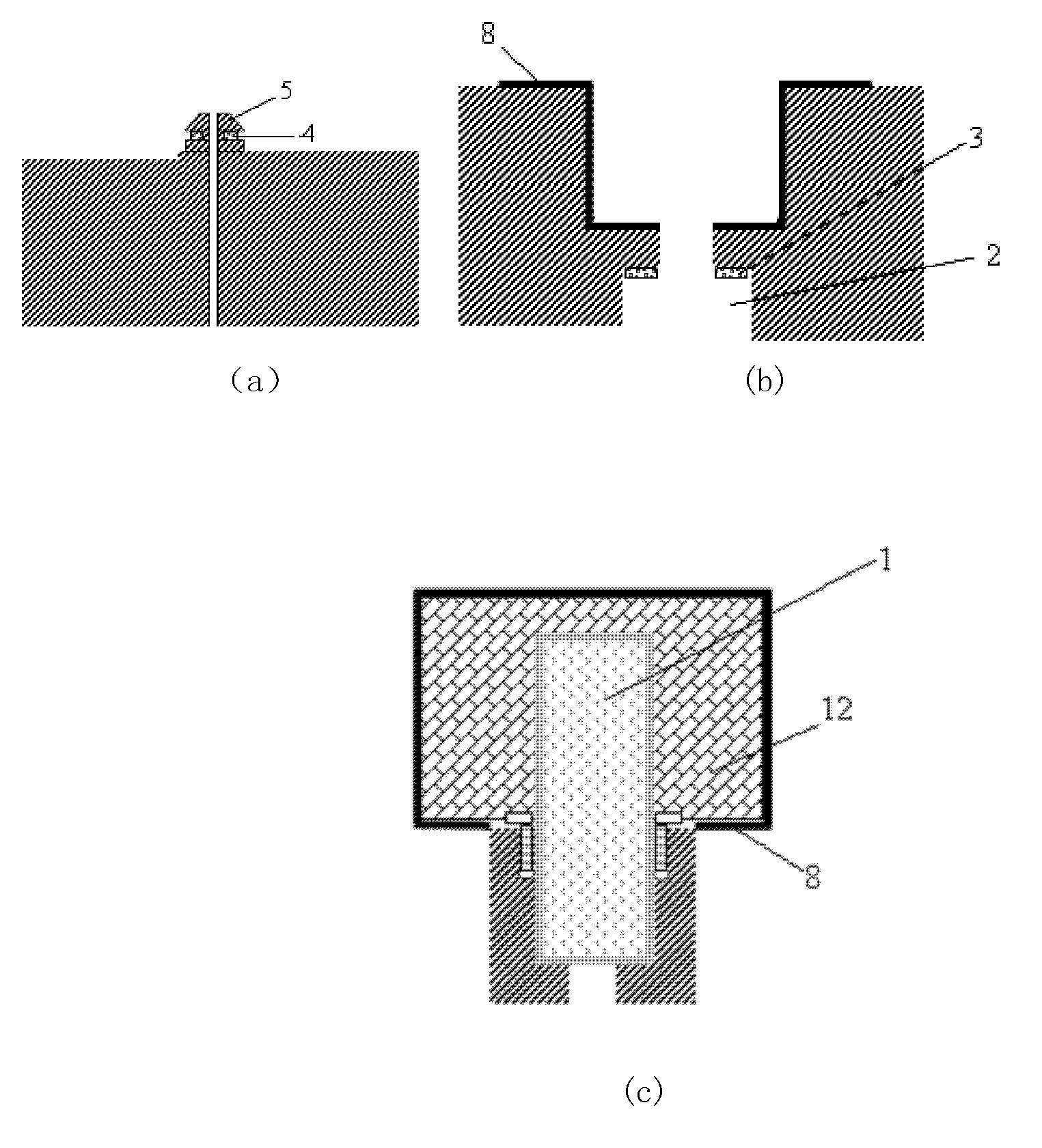
The invention discloses a high sensitivity photoionization detector, which comprises: a collector, an emitter and a nozzle in a photoionization ionization chamber. The ultraviolet light emitted by a vacuum ultraviolet lamp is directly projected to the nozzle. The collector is very close to the inner wall of the photoionization ionization chamber. The emitter is embedded into a groove in the middle of the nozzle. Ultraviolet light cannot be directly projected to surfaces of the collector and the emitter. A direct current high voltage source is loaded between the collector and the emitter to form an electric field. After being separated by a chromatographic column, a mixed gas enters the photoionization ionization chamber through the nozzle to be ionized into positive and negative ions by the vacuum ultraviolet lamp. Under the action of the electric field, the positive and negative ions are captured respectively by the collector and the emitter and converted into weak current signals, and after amplification by a microcurrent amplifier, the signals are output to a data acquisition card. The photoionization detector provided by the invention has a tiny pool volume and ultra-low noise interference, sensitivity of the detector is improved and the detection limit of the detector is lowered.

Description

technical field [0001] The invention relates to the technical field of gas detection, in particular to a high-sensitivity photoionization detector for the detection of mixed gas components. Quality monitoring, home safety, food safety, drug detection and cancer prediction and other fields. Background technique [0002] Among the gas detectors, the photoion detector has the characteristics of wide detection range, low detection limit and fast analysis speed, and has become a very important analytical detector. Its working principle is that the mixed gas is separated by the chromatographic column and brought into the photoionization ionization chamber by the carrier gas, bombarded by the ultraviolet light emitted by the UV ultraviolet lamp, and ionized into positive and negative ions. Under the action of the electric field formed by the collector and the emitter, the positive and negative ions Negative ions are captured by the collector and emitter respectively to form a weak...

Claims


Application Information

Patent Timeline
Patent Type & Authority Applications(China)
IPC IPC(8): G01N30/74
Inventor 崔大付孙建海张璐璐陈兴李辉任艳飞
Owner AEROSPACE INFORMATION RES INST CAS
Learn More