
scr denitrification device

A denitration and catalyst technology, applied in the field of flue gas denitrification, can solve the problems of insufficient space available for boilers and dust collectors, reduced catalytic effect, and inability to extract denitrification, etc., and achieves denitration treatment, good denitrification treatment, and increased catalytic efficiency. Effect

Active Publication Date: 2016-08-17
北京水木清源环保科技有限公司
View PDF5 Cites 0 Cited by
  • Summary
  • Abstract
  • Description
  • Claims
  • Application Information

AI Technical Summary

Problems solved by technology

The denitrification effect of the SCR process is better, but the investment is large, and the catalyst module is required to have good anti-pollution ability to resist SO 2 and H 2 The adverse effects of O; at the same time, it is also required to have good thermal shock resistance and mechanical strength properties
In addition, because the SCR reactor needs to be installed between the boiler and the dust collector, and the SCR reactor is large in size, there is not enough space between the boiler and the dust collector in the old power plants in my country, so the SCR process cannot be used for denitrification
Moreover, the existing SCR system still has the defect that the catalytic effect decreases rapidly after working for a period of time

Method used

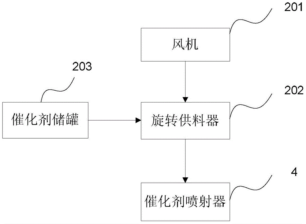
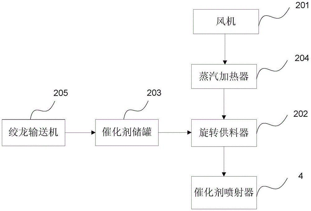

Image

  • scr denitrification device
  • scr denitrification device
  • scr denitrification device

Examples


Embodiment Construction

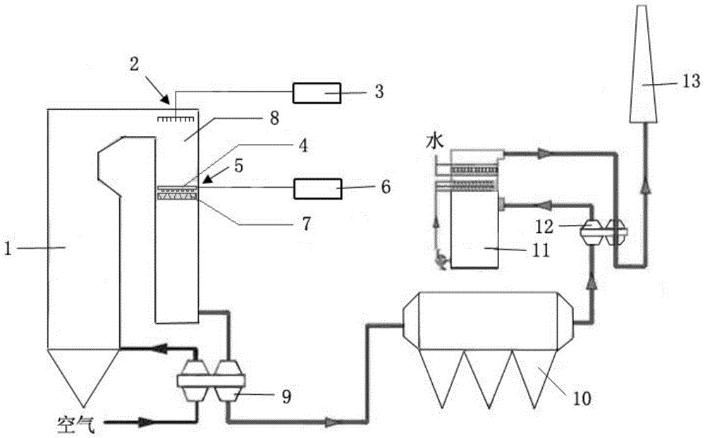
[0037] figure 1 A typical application of the SCR denitration device of the embodiment of the present invention is shown. like figure 1 As shown, the existing power plant generally includes a boiler 1, a flue 8 for exhausting flue gas, an ammonia gas storage tank 3, an air preheater 9, an electrostatic precipitator 10, an absorption tower 11, a heat exchanger 12 and a chimney 13, etc. . In a conventional SCR system, the SCR reactor is arranged between the boiler 1 and the electrostatic precipitator 10, and is arranged for a high-dust environment. The applicant found that the reason why the catalytic efficiency of the catalyst in the existing SCR reactor will drop rapidly is that, on the one hand, the large amount of soot carried in the flue gas in this area will block the pores of the catalyst; on the other hand, during the SCR operation process The catalyst is also subjected to the long-term action of alkali metals, water vapor, arsenic and other substances, resulting in ca...


PUM


Abstract

The invention provides an SCR denitration device and a flue gas denitration method. The SCR denitrification device is used to denitrify the flue gas of the boiler, the boiler has a flue for discharging flue gas, and the SCR denitrification device includes a catalyst injector for spraying powder catalyst into the flue . In the present invention, the powder catalyst is sprayed into the flue to ensure that the catalyst has the maximum reaction ability, and a small amount of catalyst can be sprayed to achieve a good denitrification effect; further, the deceleration layer is used together to prolong the residence time of the powder catalyst and increase the catalytic efficiency. The invention can flexibly adjust the injection amount of the powder catalyst according to the concentration of nitrogen oxides in the flue gas, and can be used for the treatment of violently fluctuating nitrogen oxide flue gas.

Description

technical field [0001] The invention relates to the technical field of flue gas denitration, in particular to a new SCR denitration device and a flue gas denitration method. Background technique [0002] Currently, new-build power plants typically use a selective catalytic reduction (SCR) process for denitrification. SCR denitration system generally consists of SCR reactor, catalyst module, ammonia storage and supply system, ammonia injection system, economizer bypass, SCR bypass and related test control systems. Among them, the catalyst module is placed in the flue of the SCR reactor in the form of a fixed bed, and in the upstream area of ​​the catalyst fixed bed, NH 3 It is sprayed into the flue to mix with the flue gas. When the flue gas flows through the catalyst fixed bed, NH 3 Reacts with nitrogen oxides in flue gas with the participation of catalysts to generate N 2 , to achieve denitrification. The SCR process has better denitration effect, but the investment is...

Claims


Application Information

Patent Timeline
Patent Type & Authority Patents(China)
IPC IPC(8): B01D53/90B01D53/56B01D53/79
Inventor 王盛林寿眉王涛倪云峰
Owner 北京水木清源环保科技有限公司
Learn More