Molding device for bridge-cutting-free heat-insulation aluminum profiles
A forming device and aluminum profile technology, which is applied in the field of cutting-free bridge heat-insulating aluminum profile forming devices, can solve the problems of extruding molds and equipment difficulty and cost reduction, large energy consumption, and low production efficiency, so as to avoid bridge cutting equipment , simplification of process, equipment difficulty and cost reduction effect
- Summary
- Abstract
- Description
- Claims
- Application Information
AI Technical Summary
Problems solved by technology
Method used
Image
Examples
specific Embodiment approach 1
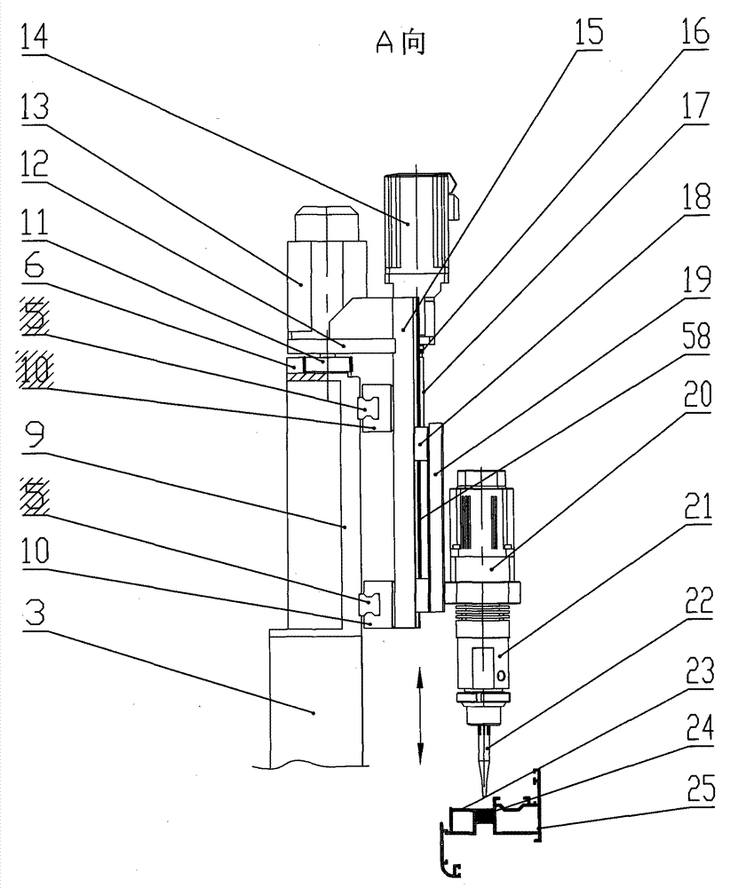
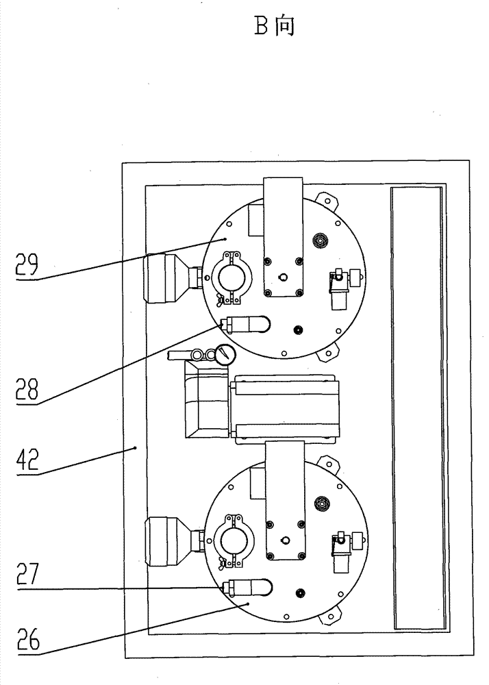
[0014] Specific implementation mode one: as Figure 1-11 As shown, the cutting-free bridge heat-insulating aluminum profile forming device of the present invention is composed of a frame 1, a conformal fixture 4, a glue supply system 8, and a glue injection head 7; the frame 1 includes an air inlet nozzle 2, a column 3, Linear guide rail A5, rack 6, rail seat 9, slider A10, gear 11, motor fixing plate 12, motor A13, motor B14, sliding seat 15, coupling 16, lead screw 17, slider B18, glue injection head Seat 19, linear guide rail B58, air intake valve 45; Follow-the-shaped clamp 4 comprises air intake 46, horizontal clamping cylinder 30, clamping plate 31, vertical clamping cylinder 32, vertical pendulum block 33, blocking 34, vertical clamping Clamping block A35, vertical clamping block B36, horizontal clamping block A37, horizontal clamping block B38, bottom plate A39, aluminum alloy support 40, bottom plate B41, base 55, base 63, aluminum profile A23, aluminum profile B25; g...
specific Embodiment approach 2
[0015] Specific implementation mode two: as figure 1 As shown, the molding device described in the present embodiment also includes a transmission wheel A59 and a rotating shaft 60, which are used to drive the conformal clamp 4. A plurality of transmission wheels A59 are installed on the rotating shaft 60 (8 among the figures), and the transmission wheels A59 and There can be N such driving shafts formed by the rotating shaft 60, and they are arranged horizontally, and the conformal fixture 4 is placed on the transmission wheel A59, and the upper surface of the transmission wheel A59 contacts with the lower surface of the base plate B41 of the conformal fixture 4, and rotates When the shaft 60 rotates, it drives the transmission wheel A59 to rotate, and drives the conformal fixture 4 to move. The conformable fixture 4 is fixed when pouring the polyurethane heat insulating strip A24. Move in the vertical direction of the axis. Other components and connections are the same as ...
specific Embodiment approach 3
[0017] Specific implementation mode three: as Figure 11 As shown, the molding device described in this embodiment will figure 1 The driving wheel A59 and the rotating shaft 60 are removed and replaced with the driving wheel B61, the wheel frame of the driving wheel B61 is connected with the frame 1, the number of driving wheels B61 can be M, and they are arranged horizontally, and the conformal fixture 4 is placed on the driving wheel On B61, the upper surface of the transmission wheel B61 contacts with the lower surface of the base plate B41 of the conformal fixture 4. When the transmission wheel B61 rotates, it drives the conformal fixture 4 to move. Shaped fixture 4 can move horizontally. Other compositions and connections are the same as those in Embodiments 1 and 2.
[0018] Wherein M is a natural number, and the value of N may be 2≤M≤100.
PUM
 Abstract
Description
Claims
Application Information
 - R&D
- Intellectual Property
- Life Sciences
- Materials
- Tech Scout
- Unparalleled Data Quality
- Higher Quality Content
- 60% Fewer Hallucinations
Browse by: Latest US Patents, China's latest patents, Technical Efficacy Thesaurus, Application Domain, Technology Topic, Popular Technical Reports.
© 2025 PatSnap. All rights reserved.Legal|Privacy policy|Modern Slavery Act Transparency Statement|Sitemap|About US| Contact US: help@patsnap.com


