
Magneto-rheological high-precision positioning device and magneto-rheological removing function transformation method

A positioning device and high-precision technology, which is applied to the parts of grinding machine tools, metal processing equipment, grinding/polishing equipment, etc., can solve the problems affecting the cost and efficiency of magnetorheological processing, difficulty in smoothness control, and high cost. Achieve no residual stress, accurate analysis results, and good positioning accuracy

Inactive Publication Date: 2013-12-18
INST OF OPTICS & ELECTRONICS - CHINESE ACAD OF SCI
View PDF6 Cites 16 Cited by
  • Summary
  • Abstract
  • Description
  • Claims
  • Application Information

AI Technical Summary

Problems solved by technology

However, the imported optical materials used in the high-precision optical system are relatively expensive, and the cost of using the same material for the removal function is high. At the same time, in the production process, materials such as zinc selenide and Si are relatively soft, and it is difficult to control the finish. Using this material to obtain the removal function, The stability is usually less than 70%, which directly affects the processing cost and efficiency of magnetorheological production

Method used


Image

  • Magneto-rheological high-precision positioning device and magneto-rheological removing function transformation method
  • Magneto-rheological high-precision positioning device and magneto-rheological removing function transformation method
  • Magneto-rheological high-precision positioning device and magneto-rheological removing function transformation method

Examples


Embodiment Construction

[0050] Below in conjunction with accompanying drawing and specific embodiment, the present invention is further explained:

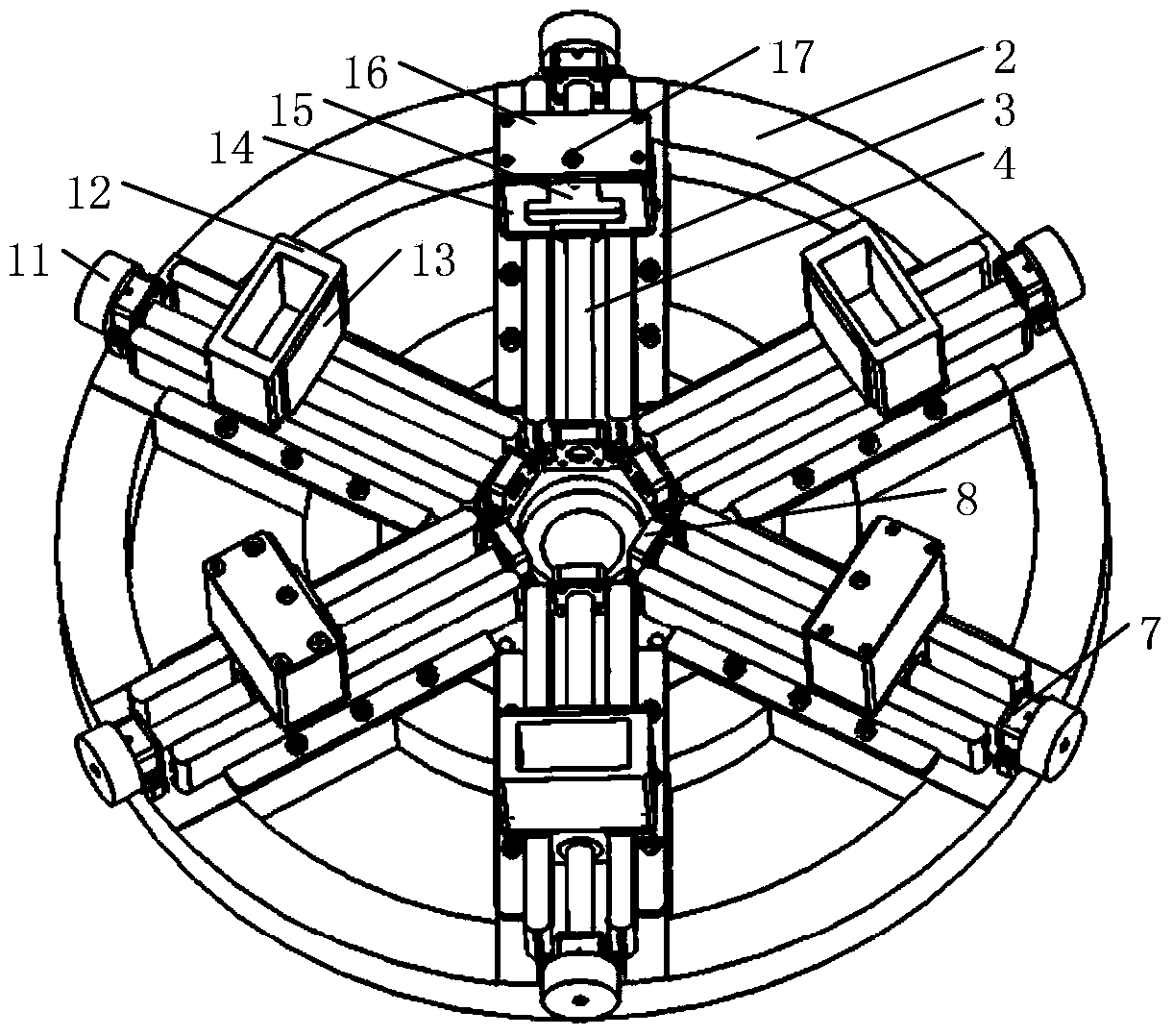
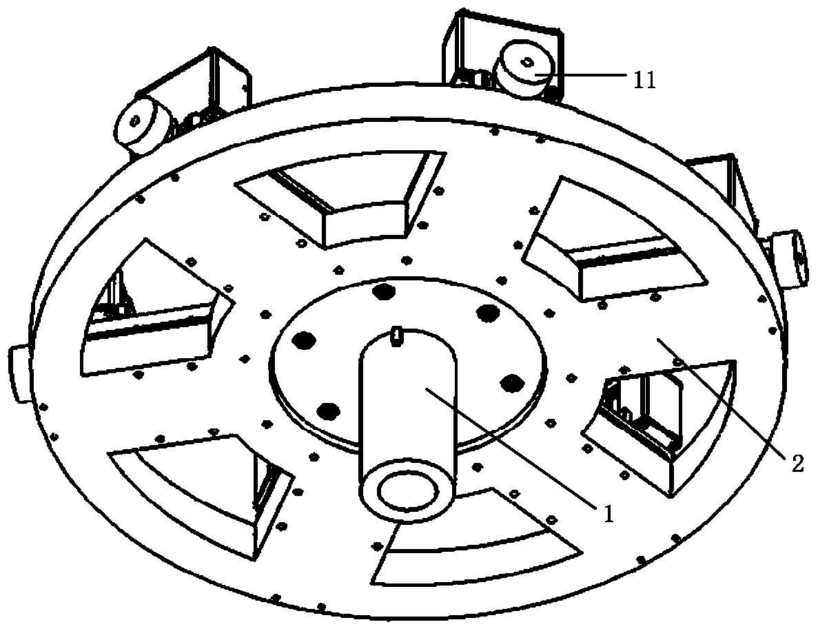
[0051] Such as figure 1 , 2 As shown, the magnetorheological high-precision positioning device of the present invention includes a fixed support mechanism, an outer circular positioning mechanism, and an end face positioning mechanism. The outer circular positioning mechanism passes through the guide rail 3, the first screw positioning frame 7, and the second screw positioning frame 8. Connected to the fixed support mechanism, the end face positioning mechanism is fixed on the positioning base 6 of the outer circle positioning mechanism through the end face positioning frame 14 .

[0052] Wherein: the fixed support mechanism, the model mainly includes a conical disc 1 and a chassis 2 . The conical disc 1 and the chassis 2 are connected as a whole by bolts, and the lower end surface of the conical disc 1 protrudes from two hubs, and the entire magnetorh...


PUM


Abstract

The invention discloses a magneto-rheological high-precision positioning device and a magneto-rheological removing function transformation method. The device comprises a fixed supporting mechanism, an excircle positioning mechanism and an end surface positioning mechanism. The method comprises the following steps of selecting an optical element substrate which is conventionally processed to measure single point removing efficiency, establishing a removing efficiency contrast coefficient library, measuring the removing efficiency of four points by using a microcrystal material, converting the removing efficiency into the removing efficiency of a workpiece to be processed, adjusting the positions of the excircle positioning mechanism, the end surface positioning mechanism and a slide block through a hand wheel and a screw rod, placing the workpiece, performing emulating calculation on the workpiece surface error through the converted removing efficiency of the workpiece to be processed, and fitting a production machine tool code to perform numerical control machining. The magneto-rheological high-precision positioning device has the advantages of high integration level and high positioning precision as well as improving removing function accuracy, shortening measuring time, improving processing efficiency, reducing processing material cost and the like and can be used for quickly processing plane and high-gradient spherical surface, non-spherical surface and free spherical surface optical elements.

Description

technical field [0001] The invention relates to the technical field of high-precision machining of magnetorheological technology, in particular to a magnetorheological high-precision positioning device and a magnetorheological removal function conversion method. The supporting device and method can be applied to plane, spherical, aspherical and free Surface and other optical components processing. Background technique [0002] With the continuous development of the performance of modern optical systems, the quality requirements of optical components are also continuously improved. In order to improve the imaging quality of the optical system and reduce the cost, modern optical parts are developing towards the trend of aspheric surface, large relative aperture and nanometer precision. For example, the 193nm deep ultraviolet lithography system requires the surface shape accuracy of high-steep spherical surfaces and high-order aspheric surfaces to be less than RMS2nm, and the ...

Claims


Application Information

Patent Timeline
IPC IPC(8): B24B1/00B24B41/00
Inventor 钟显云万勇建施春燕杨金山陈辉
Owner INST OF OPTICS & ELECTRONICS - CHINESE ACAD OF SCI
Learn More