
Electroplating and polishing grinding head with flexible layer

A polishing grinding and flexible layer technology, which is applied in the direction of grinding head, grinding/polishing equipment, grinding machine tool parts, etc., can solve the problems of cost, large positioning error, and change of the shape of the electroplating substrate, so as to reduce the use cost and achieve good The effect of positioning accuracy

Active Publication Date: 2020-03-31
CHONGQING UNIV
View PDF7 Cites 0 Cited by
  • Summary
  • Abstract
  • Description
  • Claims
  • Application Information

AI Technical Summary

Problems solved by technology

[0003] For the polishing of complex curved surfaces, due to the large curvature changes on the surface, irregularity and uneven margin after milling, it is easy to cause ordinary grinding wheels to be squeezed and broken. Although the polishing of electroplated grinding wheels will not break, but hard-to-hard polishing, vibration , high noise and prone to grinding burns; in addition, it is impossible to find a suitable rigid conjugate surface abrasive tool for high-efficiency processing of line or surface contact on complex curved surfaces. To achieve high-efficiency processing of surface contact, only flexible grinding heads are used , but generally flexible grinding heads (such as airbag polishing and rubber abrasives) have low abrasive consolidation strength, wear quickly during processing, and will produce transverse bending deformation and thermal deformation during high-speed polishing when heated under pressure. See Image 6 and Figure 7 , especially for difficult-to-machine materials with high strength and hardness, the situation will be more serious, and the positioning error will be large during processing, which will affect the processing efficiency, processing accuracy and surface quality consistency
[0004] For conventional electroplated grinding wheels, the used electroplated grinding wheel needs to be treated with acid before re-plating abrasives, and the follow-up treatment is cumbersome
In addition, because the abrasive wear is difficult to predict, the electroplating base metal may be worn during grinding, which will change the shape of the electroplating base and cannot be directly used for repeated electroplating (requires secondary machining to produce the correct shape) or scrapped, resulting in additional costs and high use costs.

Method used


Image

  • Electroplating and polishing grinding head with flexible layer
  • Electroplating and polishing grinding head with flexible layer
  • Electroplating and polishing grinding head with flexible layer

Examples


Embodiment 1

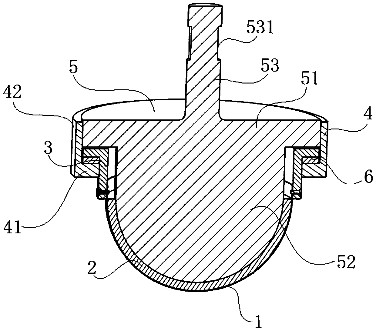
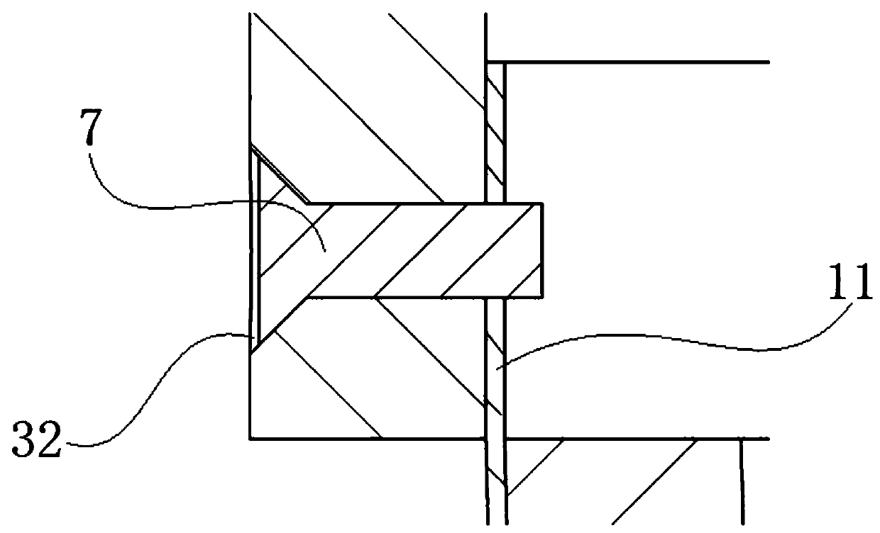
[0044] This embodiment discloses an electroplating polishing grinding head with a flexible layer, see Figure 1 to Figure 5 , including the metal outer layer 1 of the hemispherical shell, the flexible inner layer 2 of the hemispherical shell, the connecting seat cover 3 , the locking sleeve 4 and the rigid support seat 5 .

[0045] The metal outer layer 1 of the hemispherical shell is a hemispherical spring steel sheet or a mild steel sheet. The metal outer layer 1 of the hemispherical shell is formed by hot stamping. In this embodiment, the thickness of the metal outer layer 1 of the hemispherical shell is 0.3mm. The outer surface of the metal outer layer 1 of the hemispherical shell is electroplated with a polishing layer. A connecting portion 11 protrudes from the end surface of the metal outer layer 1 of the hemispherical shell. In this embodiment, the connecting portion 11 is a cylinder with a cylinder height of 8 mm, and two positioning holes 111 with a diameter of 1....

Embodiment 2

[0060] This embodiment discloses a relatively basic implementation method, an electroplating and polishing grinding head with a flexible layer, see Figure 1 to Figure 5 , including the metal outer layer 1 of the hemispherical shell, the flexible inner layer 2 of the hemispherical shell, the connecting seat cover 3 , the locking sleeve 4 and the rigid support seat 5 .

[0061] The outer surface of the metal outer layer 1 of the hemispherical shell is electroplated with a polishing layer. A connecting portion 11 protrudes from the end surface of the metal outer layer 1 of the hemispherical shell.

[0062] The flexible inner layer 2 of the hemispherical shell is attached to the inner metal outer layer 1 of the hemispherical shell. The structural rigidity of the flexible inner layer 2 of the hemispherical shell is greater than the structural rigidity of the metallic outer layer 1 of the hemispherical shell. The dimensional deformation elasticity of the flexible inner layer 2 of...

Embodiment 3

[0072] The main structure of this embodiment is the same as that of Embodiment 2. Further, a pre-tightened rubber gasket 6 is placed between the ring flange I31 and the ring flange II41.


PUM

PropertyMeasurementUnit
Particle sizeaaaaaaaaaa
Thicknessaaaaaaaaaa
Thicknessaaaaaaaaaa

Abstract

The invention discloses an electroplating and polishing grinding head with a flexible layer. The electroplating and polishing grinding head comprises a hemispherical shell metal outer layer, the hemispherical shell flexible inner layer, a connecting base sleeve, a locking sleeve and a rigid supporting base. A polishing layer is electroplated on the outer surface of the hemispherical shell metal outer layer. The hemispherical shell flexible inner layer is attached to the interior of the hemispherical shell metal outer layer. A cylinder of the hemispherical shell metal outer layer is installed in an opening of the lower end of the connecting base sleeve. The rigid supporting base comprises a connecting part, a built-in part and a metal handle. The connecting part is inserted in the locking sleeve and tightly presses the connecting base sleeve. The lower end of the metal handle is connected to the center of the upper end face of the connecting part. The upper end of the built-in part is connected to the center of the lower end face of the connecting part. The built-in part is inserted in the connecting base sleeve. A hemispherical part of the lower end of the built-in part is insertedin the hemispherical shell flexible inner layer and tightly presses the hemispherical shell flexible inner layer. The position, making contact with a workpiece, of the electroplating and polishing grinding head slightly deforms, local surface contact is realized, no trimming or wear compensation needs to be considered, and thus the electroplating and polishing grinding head has high positioning precision, machining precision and machining efficiency.

Description

technical field [0001] The invention belongs to the technical field of surface processing, and in particular relates to an electroplating and polishing grinding head with a flexible layer. Background technique [0002] Electroplated grinding wheel / grinding head (cubic boron nitride CBN or diamond abrasive) is especially suitable for forming and high-speed grinding because of its better grinding performance. It is not easy to wear and break like ordinary grinding wheels, and does not need to be trimmed. Constant line speed and consistent surface quality. The electroplated grinding wheel adopts a layer of high-performance ultra-hard single-layer abrasive, which has good shape retention ability, and the error compensation caused by abrasive wear can not be considered during CNC machining. [0003] For the polishing of complex curved surfaces, due to the large curvature changes on the surface, irregularity and uneven allowance after milling, it is easy to cause ordinary grindin...

Claims


Application Information

Patent Timeline
IPC IPC(8): B24B41/00
CPCB24B41/002
Inventor 曹华军周进懂朝阳柴迎庆
Owner CHONGQING UNIV
Learn More