High-speed target tracking control method applied to photoelectric tracker

A photoelectric tracker and tracking control technology, applied in the field of servo control, can solve the problems of large tracking, difficulty in ensuring tracking accuracy, and low tracking accuracy

Active Publication Date: 2013-12-11
西安应用光学研究所
View PDF6 Cites 26 Cited by
  • Summary
  • Abstract
  • Description
  • Claims
  • Application Information

AI Technical Summary

Problems solved by technology

Although the second-order ring tracking method is relatively simple and easy to implement, this method does not involve the relevant parameters of the moving carrier and the artillery during the entire calculation process, so it cannot compensate the disturbance caused by the moving carrier and the artillery, resulting in low tracking accuracy; at the same time , this method does not introduce the target distance, but uses the same control algorithm for far and near targets, because in the actual tracking process, with the change of the target distance, the tracking angular velocity of the photoelectric tracker in the azimuth and pitch is also constantly changing , that is, for the same target, the closer the tracking distance is, the greater the tracking angular velocity of azimuth and pitch will be. Therefore, the traditional second-order ring tracking method will produce a larger tracking lag
[0005] In the actual application process, the traditional second-order ring tracking method has a good tracking effect on the slow incoming target whose target distance cannot be obtained and whose moving speed is lower than Mach 2; In the process of tracking the incoming target, as the distance of the target decreases continuously, the tracking dynamic lag is inevitable. In addition to the disturbance of vehicle shaking, ship shaking, turret rotation and artillery shooting, the tracking accuracy is difficult to guarantee, which will affect the Shooting accuracy of the entire weapon system

Method used


Image

  • High-speed target tracking control method applied to photoelectric tracker
  • High-speed target tracking control method applied to photoelectric tracker
  • High-speed target tracking control method applied to photoelectric tracker

Examples


Embodiment Construction

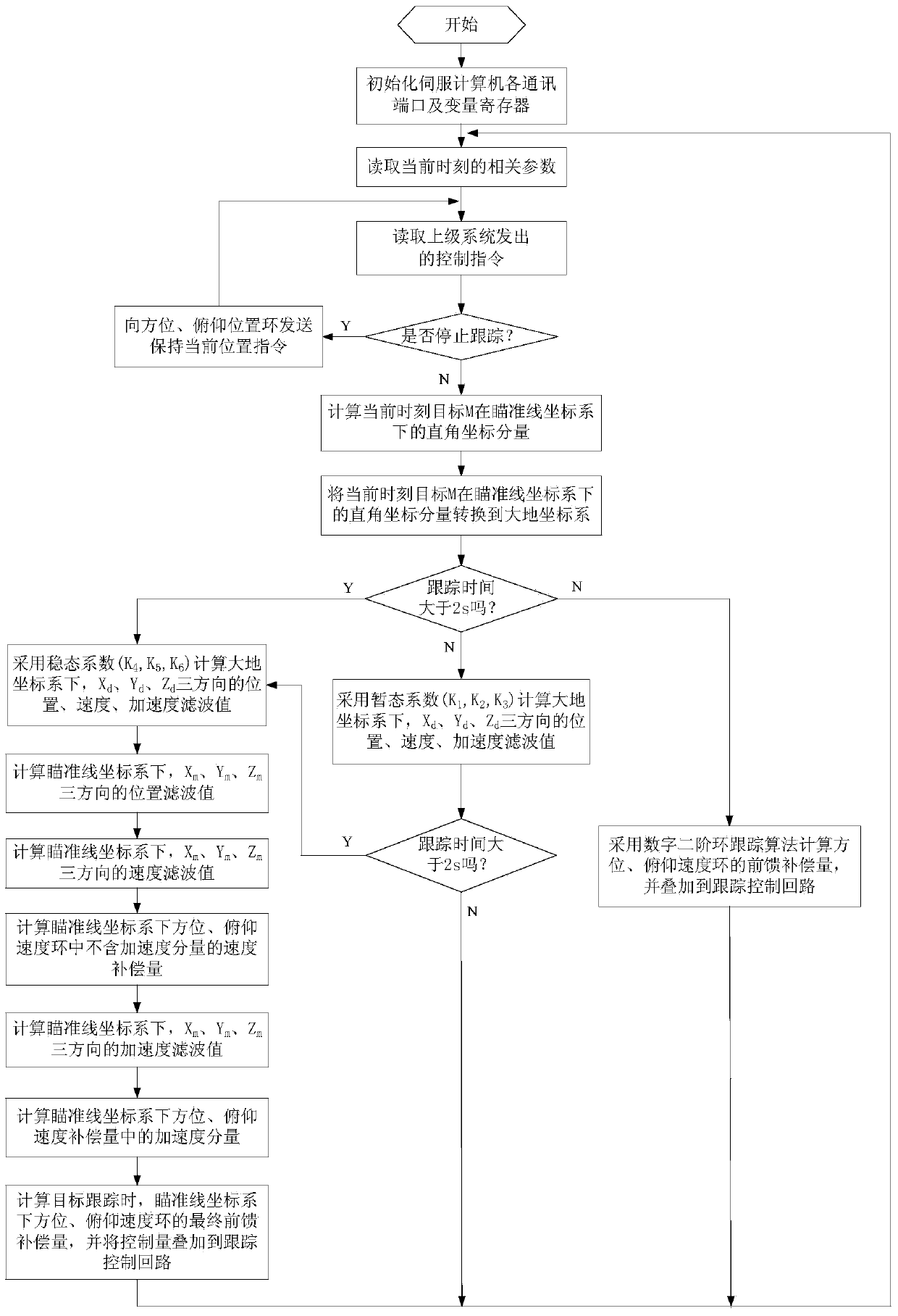
[0085] The present invention will be further described in detail below in conjunction with the accompanying drawings and preferred embodiments.

[0086] The preferred embodiment of the tracking control method of the present invention is used for a vehicle-mounted photoelectric tracker in the form of a complex. The photoelectric tracker has a two-axis and two-frame structure, which are the azimuth axis (frame) and the pitch axis (frame). The pitch frame is installed on the azimuth frame, and the laser rangefinder and video detector are installed on the optical bench of the pitch frame. Above, the azimuth and pitch frames are installed with their respective resolvers, the azimuth rate gyroscope and the pitch rate gyroscope are both installed on the pitch frame, the line of sight of the photoelectric tracker is parallel to the visual axis of each detector; the photoelectric tracker is installed on the turret The zero point of the sight line is consistent with the zero point of th...


PUM


Abstract

The invention discloses a high-speed target tracking control method applied to a photoelectric tracker, and belongs to the technical field of servo control. Relevant parameters outputted from the photoelectric tracker, artillery, a carrier inertial navigation system, a video tracker and a laser range finder are utilized, calculation of tracking feedforward compensating parameters of an orientation speed ring and a pitching speed ring below an aiming line coordinate system is completed through a series of coordinate transformation, recursive iteration and coordinate inverse transformation, and the parameters are respectively superimposed to an orientation and pitching tracking control loop to participate in tracking control. By the adoption of the photoelectric tracker, the high-speed target tracking control method has the advantages of being high in response speed, little in dynamic lag, high in tracking precision and good in tracking stability when the method is used for tracking an incoming high-speed moving target, is suitable for tracking high-speed moving targets such as incoming guided missiles and aircrafts by vehicle-mounted and ship-based photoelectric tracking systems, and has great significance in improvement of target resolving precision of fire control systems and operational effectiveness of the whole weapon system.

Description

technical field [0001] The invention belongs to the technical field of servo control and relates to a photoelectric tracker, in particular to a high-speed target tracking control method suitable for a photoelectric tracker. Background technique [0002] Nowadays, photoelectric trackers in the form of vehicle-mounted and ship-borne complexes (the photoelectric tracker is installed on the artillery turret, and the zero position of the line of sight of the photoelectric tracker is consistent with the zero position of the muzzle pointing of the artillery), usually adopts two axes of azimuth and pitch Stabilization system, that is, there is no special stabilization platform to isolate the influence of vehicle body and ship movement, but the base of the photoelectric tracker is directly consolidated with the turret, and the azimuth and pitch rate gyros are installed on the pitch frame , through the azimuth and pitch servo system, the pointing stability of the photoelectric tracker...

Claims


Application Information

Patent Timeline
IPC IPC(8): G05D1/12F41G3/06
Inventor 慕巍赵振海陆培国王小齐李晶娣江涛张宝宜王若亮李志宇王晓天柳秋兴
Owner 西安应用光学研究所
Why Eureka
Try Eureka