Energy system
A technology of energy and generation part, applied in the field of energy system
- Summary
- Abstract
- Description
- Claims
- Application Information
AI Technical Summary
Problems solved by technology
Method used
Image
Examples
Deformed example 1
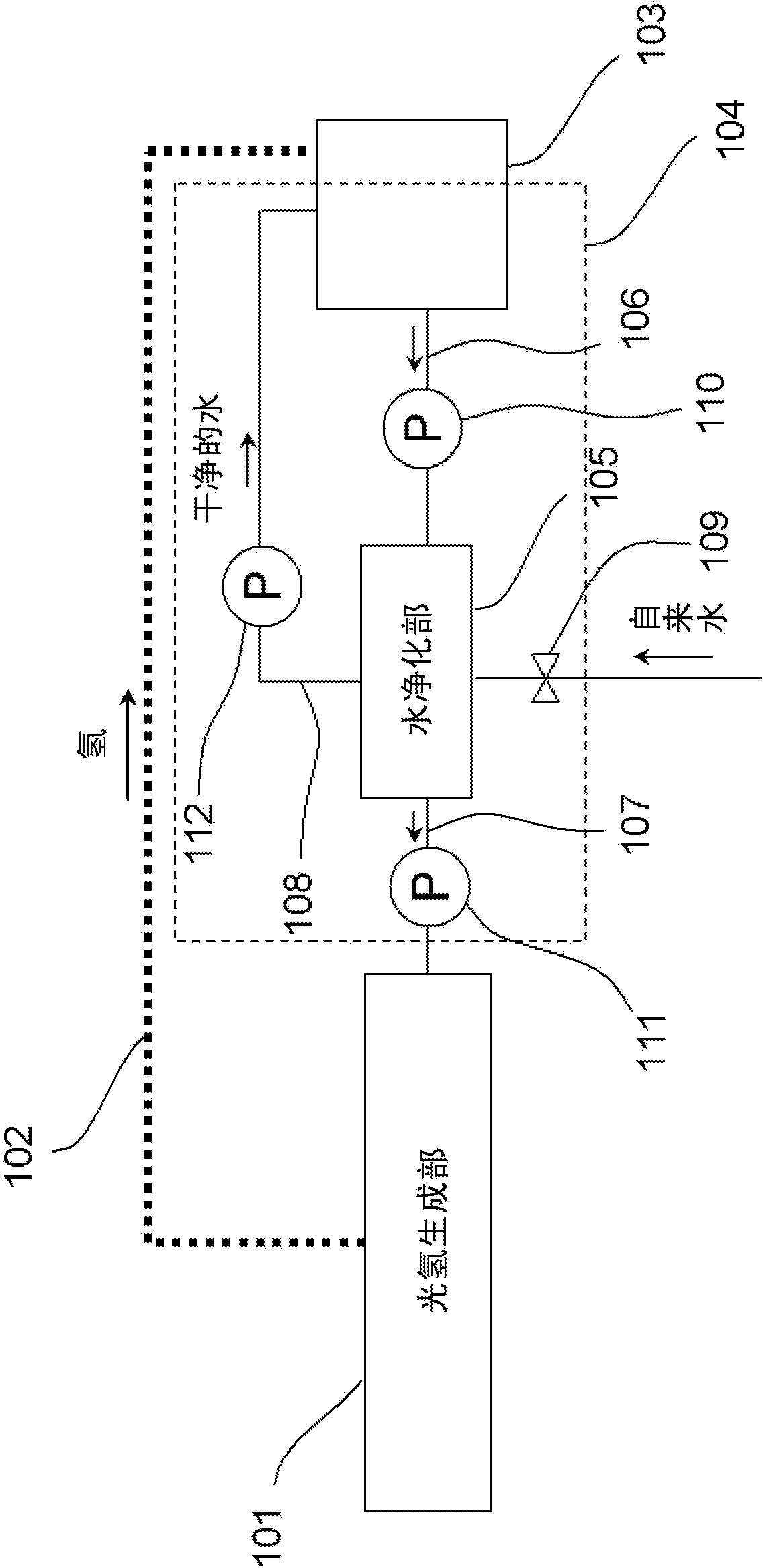
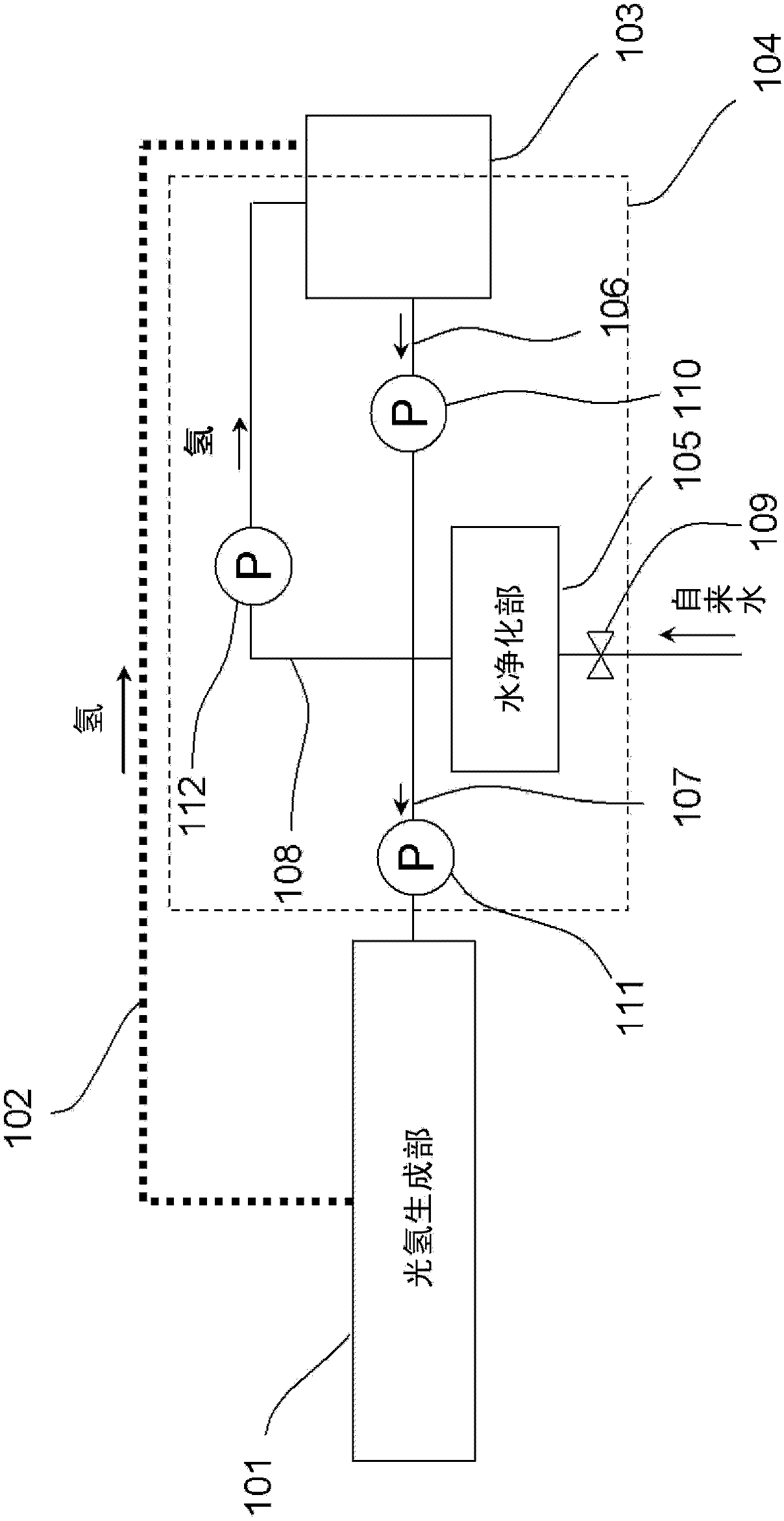
[0078] Below, refer to image 3 , Modification 1 of the energy system of this embodiment will be described. exist image 3 in, for with Figure 1A The same structural elements use the same symbols, and descriptions are omitted. In addition, the following embodiment is an example, and this invention is not limited to the following embodiment.
[0079] image 3 It is a figure which shows a modification example of the energy system in embodiment of this invention. The hydrogen distribution mechanism 102 includes a hydrogen storage facility 301 . The hydrogen storage facility 301 stores hydrogen produced by the solar hydrogen production unit 101 and supplies the hydrogen to the fuel cell 103 . The hydrogen storage device 301 may be a container such as a can, or may be a storage form using a chemical method such as a hydrogen storage alloy.
[0080] In hydrogen generation by water splitting using a photocatalytic semiconductor electrode, water splitting can only proceed when ...
Deformed example 2
[0084] Below, refer to Figure 4 , Modification 2 of this embodiment will be described. exist Figure 4 in, for with Figure 1A as well as image 3 The same structural elements use the same symbols, and descriptions are omitted.
[0085] In addition, the following embodiment is an example, and this invention is not limited to the following embodiment.
[0086] Figure 4 It is a figure which shows one structural example of the energy system in embodiment of this invention. The water distribution mechanism 104 of the energy system in this modified example further has a water storage device 401 . The water storage facility 401 can temporarily store water that is a reaction product discharged from the fuel cell 103 . The water storage facility 401 is provided on the first path 106 between the downstream side of the cathode chamber of the fuel cell 103 and the water purification unit 105 in the water distribution mechanism 104 .
[0087] In this energy system, the photovolta...
Deformed example 3
[0096] Below, refer to Figure 5A as well as Figure 5B , Modification 3 of the present embodiment will be described. exist Figure 5A as well as Figure 5B in, for with Figure 1A , Figure 3-4 The same structural elements use the same symbols, and descriptions are omitted.
[0097] In addition, the following embodiment is an example, and this invention is not limited to the following embodiment.
[0098] Figure 5A as well as Figure 5B It is a figure which shows a modification example of the energy system in embodiment of this invention.
[0099] exist Figure 5AAmong them, a first cooler 501 is provided on the first path 106 in the water distribution mechanism 104 . The first cooler 501 cools water that is a reaction product discharged from the fuel cell 103 .
[0100] The water discharged from the fuel cell 103 becomes high in temperature due to heat generated when the fuel cell 103 generates power. On the other hand, the band gap of the photocatalytic semicond...
PUM
 Abstract
Description
Claims
Application Information
 - Generate Ideas
- Intellectual Property
- Life Sciences
- Materials
- Tech Scout
- Unparalleled Data Quality
- Higher Quality Content
- 60% Fewer Hallucinations
Browse by: Latest US Patents, China's latest patents, Technical Efficacy Thesaurus, Application Domain, Technology Topic, Popular Technical Reports.
© 2025 PatSnap. All rights reserved.Legal|Privacy policy|Modern Slavery Act Transparency Statement|Sitemap|About US| Contact US: help@patsnap.com


