cutting device

A technology of cutting devices and cutting tools, which is applied in the direction of fine working devices, working accessories, manufacturing tools, etc., and can solve the problems of high cost and poor productivity

Active Publication Date: 2020-01-31
DISCO CORP
View PDF6 Cites 0 Cited by
  • Summary
  • Abstract
  • Description
  • Claims
  • Application Information

AI Technical Summary

Problems solved by technology

[0005] However, pure water is used as the cutting water supplied to the cutting portion of the cutting tool by the cutting member, which has the problems of high cost and low productivity.

Method used


Image

  • cutting device
  • cutting device

Examples


Embodiment Construction

[0013] Hereinafter, preferred embodiments of the cutting device according to the present invention will be described in further detail with reference to the drawings.

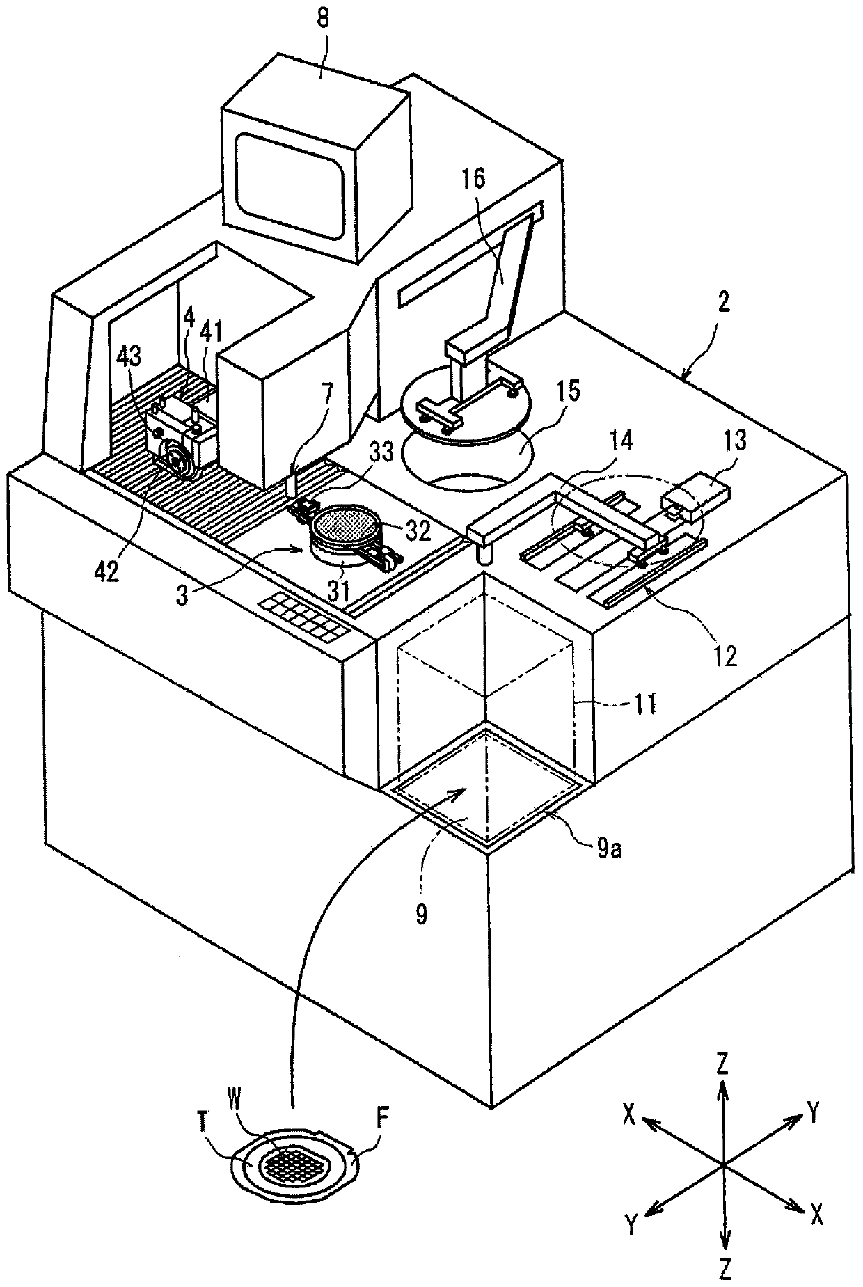
[0014] figure 1 A perspective view of a cutting device constructed in accordance with the present invention is shown in . figure 1 The cutting device shown has a substantially cuboid device housing 2 . In the device case 2, a chuck table 3 as a workpiece holding member for holding a workpiece is arranged so as to be movable in a direction indicated by an arrow X (X-axis direction) which is a cutting feed direction. The chuck table 3 has a suction chuck support table 31 and a suction chuck 32 arranged on the suction chuck support table 31, and the suction chuck 32 is placed on top of the suction chuck 32 by operating a suction member (not shown). The holding surface of the surface attracts and holds the workpiece. In addition, the chuck table 3 is configured to be rotatable by a not-shown rotation mechanism. ...


PUM


Abstract

Provided is a cutting device capable of recovering cutting water supplied to a cutting portion of a cutting tool by a cutting member and regenerating it into water that does not damage a workpiece. The cutting device includes: a workpiece holding member that holds a workpiece; a cutting member that has a rotatable cutting blade that cuts the workpiece held on the workpiece holding member; A water supply mechanism that supplies cutting water to a cutting portion of a cutting tool based on a cutting member, the cutting device having: a cutting water receiving member that receives cutting water supplied to a cutting portion of a cutting tool based on a cutting member; A chip removing member removes chips mixed in the cutting water received by the cutting water receiving member; and a pump sends the cutting water from which chips have been removed by the chip removing member to the cutting water supply mechanism.

Description

technical field [0001] The present invention relates to a cutting device for cutting a workpiece such as a semiconductor wafer. Background technique [0002] In the manufacturing process of a semiconductor device, a plurality of regions are divided by dividing lines formed in a grid on the front surface of a substantially disk-shaped semiconductor wafer, and devices such as ICs and LSIs are formed in the divided regions. Individual semiconductor devices are manufactured by cutting the semiconductor wafer formed with a plurality of devices in this manner along planned dividing lines to divide regions where the devices are formed. [0003] A cutting device for cutting a semiconductor wafer along a planned dividing line includes: a workpiece holding member that holds a workpiece; cutting the workpiece on the surface; a cutting water supply member, which supplies cutting water to the cutting part of the cutting tool based on the cutting member; and a processing feed member, whi...

Claims


Application Information

Patent Timeline
Patent Type & Authority Patents(China)
IPC IPC(8): B28D5/02B28D7/00B28D7/02B28D7/04
CPCB28D5/0058B28D5/0076B28D5/0082B28D5/023Y02P70/10
Inventor 关家一马
Owner DISCO CORP
Why Eureka
Try Eureka