Fuel-limiting device for engine with supercharger

A limiting device and engine technology, applied in engine control, fuel injection devices, machines/engines, etc., can solve the problems of black smoke, useless fuel, consumption, etc., and achieve the effects of avoiding black smoke, reducing costs, and simplifying the composition

Inactive Publication Date: 2006-01-11
KUBOTA LTD
View PDF0 Cites 0 Cited by
  • Summary
  • Abstract
  • Description
  • Claims
  • Application Information

AI Technical Summary

Problems solved by technology

[0008] Therefore, in the previous example 1, it is necessary to set the push rod M with another purpose, so as to overcome the return spring 28 of the booster actuator 26 and push the above-mentioned gauge 21 to the starting increment position, however, The result of doing like this needs to overcome the return spring 28 of booster actuator 26 and the powerful driving force that above-mentioned push rod M is released
On the other hand, if the gauge 21 is always at the start increment position when the engine is started, excess fuel will be supplied during a hot start, resulting in problems such as the generation of black smoke or the consumption of useless fuel.
[0009] In addition, in Conventional Example 2, since the output rod 35 of the above-mentioned actuator 40 is retracted when the engine is started, the action point K of the above-mentioned swing rod 31 is incrementally moved, although the above-mentioned Conventional Example 1 is eliminated. However, since the output part 17 of the adjustment rod 14 cannot be detachedly engaged with the adjustment meter 21 of the fuel injection pump, in order to make the boost actuator 26 suppress the above-mentioned adjustment meter 21 during rapid acceleration Incremental movement, the elastic strength of the return spring 28 of the booster actuator 26 must be set to a level that can basically balance the tension of the spring 13 during rapid acceleration. Correspondingly, the diaphragm 27 also needs to have a large Pressure area
As a result, the overall size of the booster actuator 26 increases

Method used


Image

  • Fuel-limiting device for engine with supercharger
  • Fuel-limiting device for engine with supercharger
  • Fuel-limiting device for engine with supercharger

Examples


Embodiment Construction

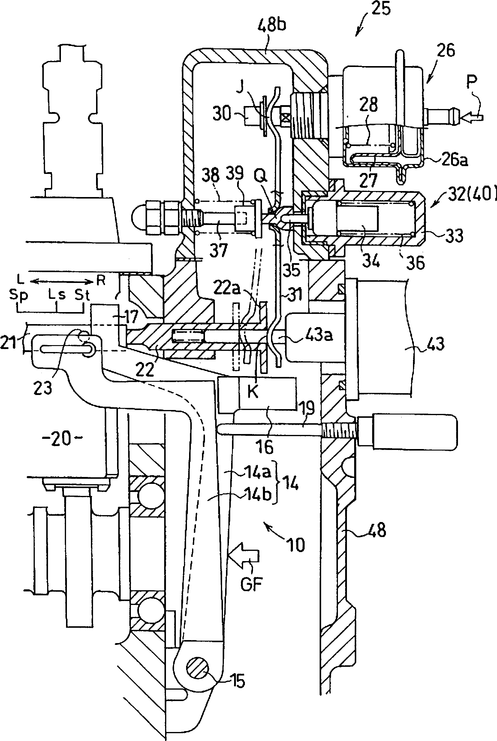
[0045] Embodiments of the present invention will be described below based on the drawings. figure 1 It is a schematic diagram of a fuel limiting device for an engine with a supercharger according to the invention described in claim 1 (hereinafter referred to as "the first invention"), figure 2 It is a vertical end view of a fuel regulating device for an engine with a supercharger according to Embodiment 1 of the first invention.

[0046] The centrifugal regulator 10 applicable to the first invention is as figure 1 and figure 2 As shown, a first rod 14a and a second rod 14b constituting a double adjusting rod 14 are provided, and a torque booster 16 is installed between the first rod 14a and the second rod 14b, which can swing integrally.

[0047] The fuel limiting device 25 of the first invention is as figure 1 and figure 2 As shown, with previous example 1 ( Figure 11 ) and previous example 2 ( Figure 12 ) basically have the same structure.

[0048] That is to s...


PUM


Abstract

A fuel-limiting device for engine with supercharger, where a fuel meter of a fuel injection pump is made movable for fuel metering through a governor lever. A swing lever has a power input point which engages with a boost actuator. A governor lever is connectably and separably opposed to the fuel meter from a fuel increase side and a start spring 18 urges the fuel meter toward a starting fuel increase side. The swing lever has a pivot axis displaceable by an actuator. When making a cold start, the actuator 40 does not operate to thereby confine the fuel meter to a starting fuel increase position by the power output point positioned on a fuel increase side. When making a warm start, the power output point positioned on a fuel decrease side confines the fuel meter to a starting fuel decrease position.

Description

technical field [0001] The present invention relates to a fuel limiting device for a diesel engine equipped with a supercharger, and particularly relates to a technology capable of ensuring a fuel boost at start-up while suppressing a fuel boost during rapid acceleration with a diaphragm booster actuator. Background technique [0002] As an engine fuel limiting device with a supercharger, conventionally known structures include, for example, Figure 11 shown (hereinafter referred to as Conventional Example 1) or Figure 12 The form shown (hereinafter referred to as Conventional Example 2). [0003] The structure of this conventional example 1 is as follows Figure 11 As shown, the gauge 21 of the fuel injection pump of the engine E with a supercharger adopts a structure in which the double adjusting rods 14 of the centrifugal regulator 10 are moved so as to adjust the volume. At the power point J of the swing rod 31 supported by the swing support shaft Q, the output rod 30 ...

Claims


Application Information

Patent Timeline
Patent Type & Authority Patents(China)
IPC IPC(8): F02D1/04F02M37/08F02D1/02F02D1/06F02D1/10F02M59/44
CPCF02D1/10F02M59/447F02D1/065F02D1/025F02D1/06F02M37/08
Inventor 吉井理辻英将坂野伦祥
Owner KUBOTA LTD
Why Eureka
Try Eureka