Magnetron electrode for plasma processing
A plasma and magnetron technology, applied in the field of magnetron electrodes for plasma processing, can solve the problems of low productivity and difficulty in increasing the film forming speed, and achieve the effect of less abnormal discharge
- Summary
- Abstract
- Description
- Claims
- Application Information
AI Technical Summary
Problems solved by technology
Method used
Image

Examples
Embodiment 1
[0036] In the magnetron sputtering electrode of the present invention, a device for changing the structure and magnetic field strength of the magnetic circuit for the magnetron, and a device for changing the opening width of the anode were produced, and a comparison of the occurrence of abnormal discharge was carried out. The results of the experiment will be described as examples, and the results of the same experiment using a magnetron sputtering electrode other than the present invention will be described as a comparative example.
[0037] First, the specific structure will be described in detail in the specification, and then the difference in structure and the difference in the occurrence status of abnormal discharge will be shown in a list.
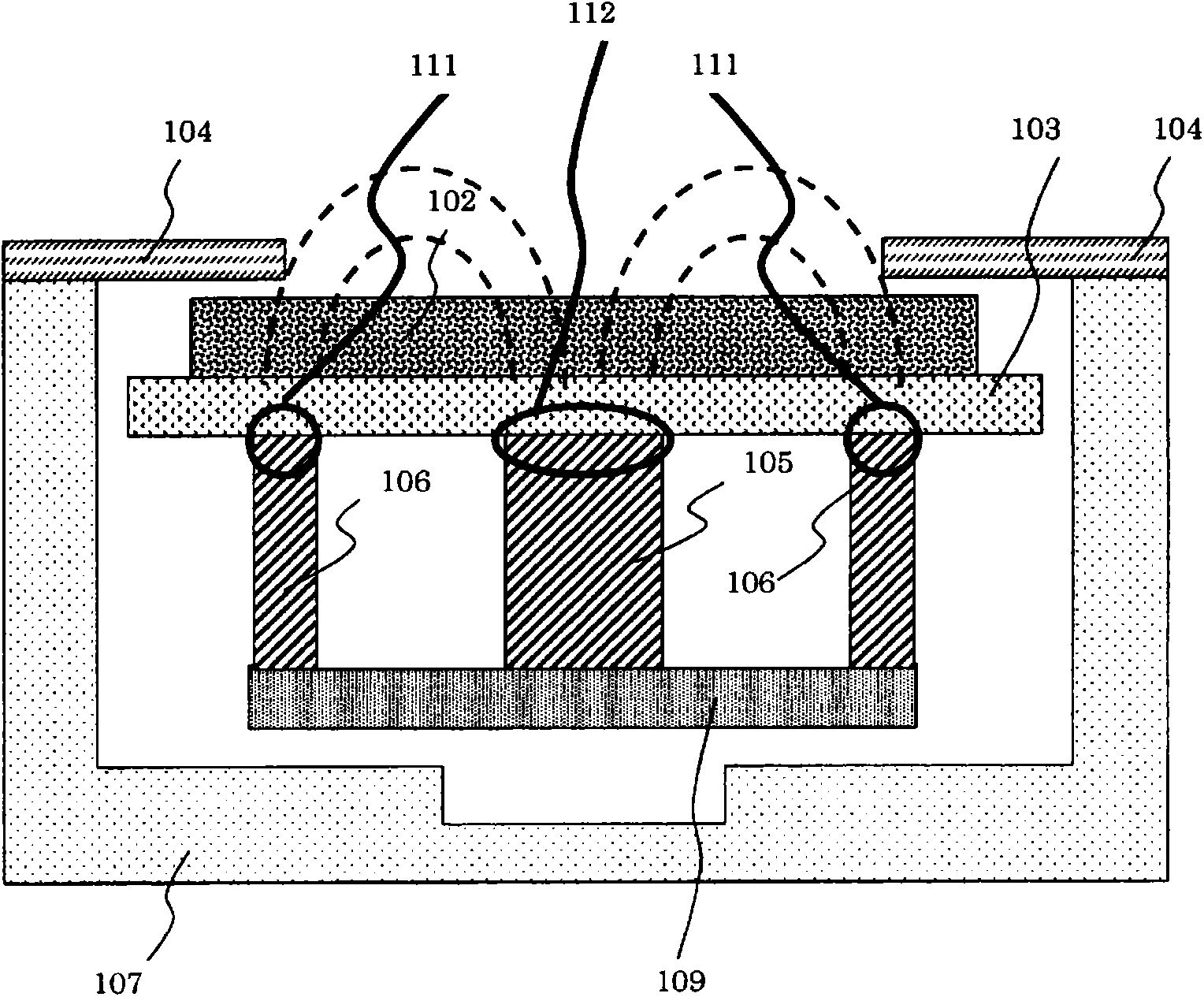
[0038] First, explain the corresponding scheme 1, Figure 3b The electrodes shown in the cross-sectional view. The cathode box is made of ferritic stainless steel SUS430. The inner dimensions of the concave part of the cathode box...
Embodiment 2
[0043] The magnetic circuit of the electrode of Example 1 was changed. Specifically, the neomagnet magnetized in the height direction with a length of 40 mm, a width of 10 mm, and a height of 20 mm arranged in the center of the cathode box in the width direction was replaced with a NeoMag company-made neodymium magnet (Grade: N35 ), and arrange them along the length direction so that the magnetization direction faces the height direction and the direction of the opening of the cathode case is the S pole, as the main magnet, and the auxiliary magnet is not used. The surface magnetic flux density of this neodymium magnet was 390 millitesla. Other electrode structures are the same as those in Example 1, and the experimental results are also shown in Table 1. In addition, the occurrence status of abnormal discharge after 3 hours from the start of discharge is also shown in this table.
Embodiment 3
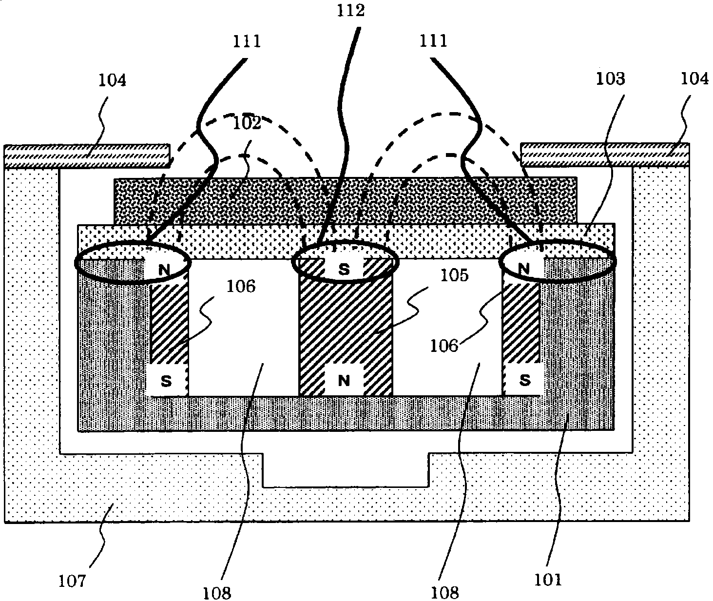
[0045] Change the magnetic circuit of the electrode of embodiment 1, become figure 1 The electrode configuration shown in the cross-sectional view. Specifically, the main magnet arranged in the center of the width direction of the cathode box is unchanged, and an anisotropic ferrite magnet manufactured by Sagami Chemical Metal Co., Ltd. with a length of 65 mm, a width of 4 mm, and a height of 19 mm is placed on the inner surface of the magnetic pole outside the cathode box so that The direction of the opening of the cathode box is set in the manner of N pole as an auxiliary magnet. The surface magnetic flux density of this anisotropic ferrite magnet was 140 millitesla. Other electrode structures are the same as those in Example 1, and the experimental results are also shown in Table 1. In addition, the occurrence status of abnormal discharge after 3 hours from the start of discharge is also shown in this table.
PUM
| Property | Measurement | Unit |
|---|---|---|
| width | aaaaa | aaaaa |
| depth | aaaaa | aaaaa |
| length | aaaaa | aaaaa |
Abstract
Description
Claims
Application Information
 - R&D
- Intellectual Property
- Life Sciences
- Materials
- Tech Scout
- Unparalleled Data Quality
- Higher Quality Content
- 60% Fewer Hallucinations
Browse by: Latest US Patents, China's latest patents, Technical Efficacy Thesaurus, Application Domain, Technology Topic, Popular Technical Reports.
© 2025 PatSnap. All rights reserved.Legal|Privacy policy|Modern Slavery Act Transparency Statement|Sitemap|About US| Contact US: help@patsnap.com