
Urea sulfate reactor and application thereof

A technology of reactor and urea sulfate, which is applied in the field of compound fertilizer, can solve the problems of high investment and operation cost, high repair and maintenance cost, high safety level requirements, etc., and achieve the effect of light weight, simple structure and high granulation quality

Active Publication Date: 2013-11-20
辽宁津大肥业有限公司
View PDF4 Cites 6 Cited by
  • Summary
  • Abstract
  • Description
  • Claims
  • Application Information

AI Technical Summary

Problems solved by technology

However, it has been found in practical production that the urea sulfuric acid reactor used in traditional urea sulfur process equipment and its matching equipment such as pipelines, pump valves, etc. are not only complex in structure, troublesome in operation, large in investment (about 400,000 yuan), and short in service life. Moreover, the heat loss in the production process is large, and it is easy to corrode. After corrosion, there are major safety hazards, and the repair and maintenance costs are high.
[0003] Patent No. 201110290323.5 discloses a urea sulfate ammoniated compound fertilizer production process. Because it uses sulfuric acid and urea to react in advance to generate urea sulfate, and then becomes a urea sulfate solution through dilution, the reaction kettle and urea sulfate used for the reaction of sulfuric acid and urea The pipeline has high requirements for corrosion resistance and a large anti-corrosion area; it also reacts with gas ammonia through a tubular reactor, which needs to be invested in an ammonia station, which requires a high level of safety and requires a series of safety facilities, making the structure of the entire equipment complex. High input and operating costs

Method used


Image

  • Urea sulfate reactor and application thereof
  • Urea sulfate reactor and application thereof
  • Urea sulfate reactor and application thereof

Examples


Embodiment 1

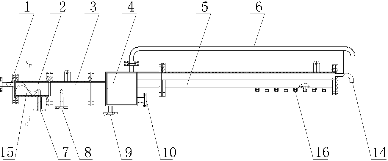
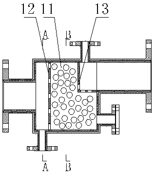
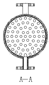
[0025] Such as Figure 1 to Figure 5 As shown, the urea sulfuric acid reactor is located in the granulator, which includes five parts: diversion section 2, mixed acid section 3, fixed bed reaction section 4, spraying pipe 5 and atomizing nozzle, and the above five parts are arranged in sequence and between each other It is fixedly connected by a flange; the urea solution pipeline is connected to the urea solution inlet port 1 of the reactor, and the urea solution inlet port 1 is located at the end side of the diversion section 2; the concentrated sulfuric acid solution pipeline is connected to the concentrated sulfuric acid inlet port 7 of the reactor , the concentrated sulfuric acid inlet port 7 is located on the side wall at the end of the diversion section 2; the fixed bed reaction section 4 is a chamber, and the chamber is separated by orifice plate I12 and orifice II13 to form a packing layer 11, the packing layer 11 Connected with the filling port 10, several through hol...

Embodiment 2

[0028] 50 (30-10-10)% compound fertilizer production process, including the following steps:

[0029] (1) Install the urea sulfuric acid reactor in the granulator, connect the urea solution pipeline to the urea solution inlet port 1 of the reactor, and connect the concentrated sulfuric acid solution pipeline to the concentrated sulfuric acid inlet port 8 of the reactor, and the solid in the granulator Materials include urea 200kg, ammonium bicarbonate 47kg, monoammonium phosphate 208kg, potassium chloride 170kg;

[0030] (2) Put 20kg of sulfuric acid and 374kg of urea solution (95°C, containing 355kg of urea) into the urea sulfate reactor through the sulfuric acid pump and the urea solution pump to react. During the reaction, a large amount of reaction heat, high temperature and viscous urea sulfate will be generated. Liquid, high-temperature molten urea and high-temperature and high-pressure steam, among which high-temperature viscous urea sulfate liquid and high-temperature ...

Embodiment 3

[0033] 54 (18-18-18)% compound fertilizer production process, including the following steps:

[0034] (1) Install the urea sulfuric acid reactor in the granulator, connect the urea solution pipeline to the urea solution inlet port 1 of the reactor, and connect the concentrated sulfuric acid solution pipeline to the concentrated sulfuric acid inlet port 8 of the reactor, and the solid in the granulator Materials include urea 150kg, ammonium bicarbonate 60kg, monoammonium phosphate 365kg, potassium chloride 285kg;

[0035](2) Put 20kg of sulfuric acid and 126kg of urea solution (97°C, containing 120kg of urea) into the urea sulfate reactor for reaction through the sulfuric acid pump and urea solution pump. During the reaction, a large amount of reaction heat, high temperature and viscous urea sulfate will be generated. Liquid, high-temperature molten urea and high-temperature and high-pressure steam, among which high-temperature viscous urea sulfate liquid and high-temperature m...


PUM


Abstract

The invention provides a urea sulfate reactor and a compound fertilizer production process by using the same. While in use, concentrated sulfuric acid and a high-temperature urea solution are proportioned, then are added into the reactor, and are in full contact with each other in a short time; a large amount of reaction heat, a high-temperature viscous urea sulfate liquid, a high-temperature molten urea and high-temperature high-pressure steam are produced by undergoing a chemical reaction, and the high-temperature viscous urea sulfate liquid and the high-temperature molten urea are atomized and sprayed into a pelleting machine through a narrow and small atomizing spray nozzle under a certain pressure; because the atomized high-temperature materials are directly sprayed on the surface of a material bed of materials in the pelleting machine, the material temperature and the liquid phase amount in the pelleting machine can be increased through contact. The materials in the pelleting machine are pelletized into pellets when the pelleting machine rotates, at the same time, the materials sprayed out from the reactor contain sulfuric acid, sulfuric acid can undergo a chemical reaction with ammonium hydrogen carbonate added in the materials and releases water and a large amount of reaction heat, so the material temperature and the liquid phase amount in the pelleting machine are also allowed to be greatly increased, and thus the materials are more easily pelletized.

Description

technical field [0001] The invention relates to a urea sulfate reactor and a compound fertilizer production process using the urea sulfate reactor, belonging to the technical field of compound fertilizers. Background technique [0002] At present, my country's compound fertilizer granulation generally adopts the steam granulation method, urine spraying method or the upgraded amino acid method. With the continuous advancement of science and technology, very few enterprises have begun to use the sulfuric acid urea ammonification spraying method. The urea sulfuric acid ammoniation spraying method is an advanced granulation method that combines the advantages of the above-mentioned various granulation methods. This method is not only suitable for the compound fertilizers that can be produced by the above-mentioned granulation methods, but also suitable for Or difficult to produce 30-10-10, 16-16-16, 17-17-17, 18-18-18, 15-5-25 and other compound fertilizers, as well as ammonium ...

Claims


Application Information

Patent Timeline
IPC IPC(8): C05G1/00
Inventor 张凤林常延龙赵海溟
Owner 辽宁津大肥业有限公司
Learn More