
Wire cable labelling machine

A labeling machine and cable technology, which is applied in the field of cable labeling machines, can solve the problems of poor cable labeling quality, inflexible overall design, and inaccurate swing positioning, so as to improve labeling quality and efficiency, Compact structure and high positioning accuracy

Active Publication Date: 2013-11-20
SHENGLAN TECH CO LTD
View PDF8 Cites 14 Cited by
  • Summary
  • Abstract
  • Description
  • Claims
  • Application Information

AI Technical Summary

Problems solved by technology

[0005] However, the swing mechanism of the existing labeling machine is often connected or transmitted by a motor. When the laminating device is heavy, in order to overcome the influence of inertia on the reaction force of the motor, the power of the motor has to be increased, so that the existing The swing mechanism has the problems of inflexible overall design, waste of resources, and inaccurate swing positioning, which makes the labeling quality of the cable poor; at the same time, the cable is placed manually and positioned by the cable itself, so the accuracy is low. In turn, the labeling quality of the cable is not good

Method used


Image

  • Wire cable labelling machine
  • Wire cable labelling machine
  • Wire cable labelling machine

Examples


Embodiment Construction

[0030] In order to describe the technical content and structural features of the present invention in detail, further description will be given below in conjunction with the implementation and accompanying drawings.

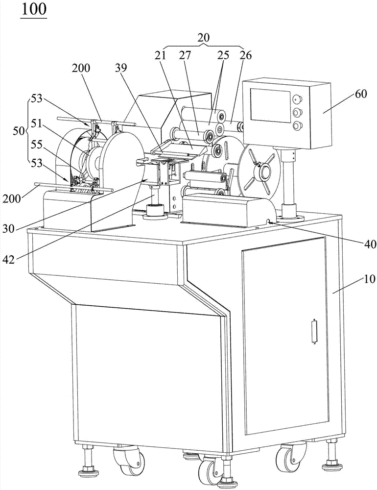
[0031] see Figure 1 to Figure 4 , the cable labeling machine 100 of the present invention is preferably electrically connected to a controller 60, so that the controller 60 can automatically control the cable labeling machine 100 of the present invention, wherein the cable labeling machine of the present invention The machine 100 includes a frame 10 , a self-adhesive conveying device 20 , a bonding device 30 , a cable conveying device 50 and a self-locking swing device 40 . Self-adhesive conveying device 20 is installed on the frame 10, and self-adhesive conveying device 20 comprises will as Figure 11 The strip-shaped self-adhesive 300 as shown is peeled off the self-adhesive label 310 (see Figure 8 ) and the peeling part 21 of the waste material 320, the peel...


PUM


Abstract

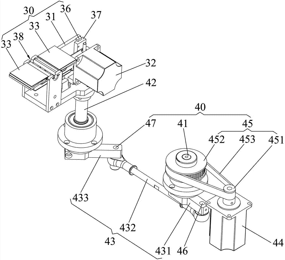
The invention provides a wire cable labelling machine. The wire cable labelling machine comprises a rack, an adhesive sticker conveying device, a bonding device, a wire cable conveying device and a self-locking type swinging device, wherein the wire cable conveying device is installed on the rack and used for conveying wire cables to the bonding device; the self-locking type swinging device comprises a first pivot shaft, a second pivot shaft, a first linkage element, a second linkage element, a third linkage element and a first driver; the first pivot shaft and the second pivot shaft are pivoted on the rack, one end of the first linkage element is installed on the first pivot shaft, the other end of the first linkage element is pivoted with one end of the second linkage element, the other end of the second linkage element is pivoted with one end of the third linkage element, the other end of the third linkage element is installed on the second pivot shaft, the first linkage element, the second linkage element, the third linkage element and the rack form a first crank rocker mechanism, the first linkage element, the second linkage element and the third linkage element correspondingly serve as a first crank, a first connection and a first rocker in the first crank rocker mechanism; the first driver is arranged on the rack and used for driving the first pivot shaft to rotate; the bonding device is installed on the second pivot shaft. The wire cable labelling machine provided by the invention is capable of improving labelling quality and efficiency for wire cables.

Description

technical field [0001] The invention relates to a labeling machine, in particular to a cable labeling machine for sticking self-adhesive labels on cables. Background technique [0002] With the continuous development of the economy and the continuous progress of science and technology, it provides strong support for the development of the cable industry, thereby accelerating the pace of development of the cable industry. [0003] In the cable industry, self-adhesive labels with identification functions are affixed to common cables, and there are two common ways for self-adhesive labels to be affixed to cables, which are purely manual labeling and labeling. The way of mechanical labeling and labeling. Due to the defects of low efficiency, high cost and poor labeling consistency in the purely manual labeling and labeling method, the purely manual labeling and labeling method is gradually replaced by the mechanical labeling and labeling method. [0004] Among them, the labeli...

Claims


Application Information

Patent Timeline
IPC IPC(8): B65C3/02B65C9/26B65C9/06
Inventor 薛树明陈成
Owner SHENGLAN TECH CO LTD
Learn More