Multi-junction solar cell with metal reflector and preparation method thereof

A technology of solar cells and metal mirrors, applied in the field of solar photovoltaics, can solve problems such as difficult operation, and achieve the effects of simple operation, strong practicability, and improved light utilization rate

Active Publication Date: 2013-10-23
JIANGSU YONGDING COMM
View PDF7 Cites 14 Cited by
  • Summary
  • Abstract
  • Description
  • Claims
  • Application Information

AI Technical Summary

Problems solved by technology

This patent document converts the wavelength by coating phosphor, increases the utilization rate of the spectrum, and improves the efficiency of the battery. This method converts the wavelength energy of sunlight and utilizes it, which is difficult to operate.

Method used


Image

  • Multi-junction solar cell with metal reflector and preparation method thereof
  • Multi-junction solar cell with metal reflector and preparation method thereof
  • Multi-junction solar cell with metal reflector and preparation method thereof

Examples


Embodiment 1

[0053] Embodiment 1, the fabrication method of the GaInP / GaAs / InGaNAs triple-junction solar cell with metal reflector, the steps are as follows:

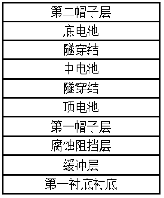
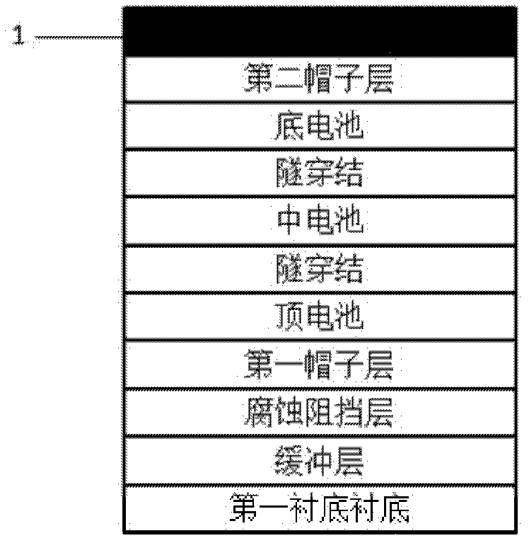
[0054] (1) The triple-junction solar cell epitaxial wafer is grown by MOCVD method, and the epitaxial wafer structure is as follows figure 1 As shown, the top cell GaInP, the middle cell GaAs, and the bottom cell InGaNAs are grown on the first substrate GaAs; the band gap of the top cell is larger than that of the middle cell, and the band gap of the middle cell is larger than that of the bottom cell.

[0055] (2) On the epitaxial wafer grown in step (1), clean the solar cell epitaxial wafer to remove surface organic matter and dirt, and vapor-deposit an ohmic contact NiAu metal layer on the surface of the second cap layer, and the thickness of NiAu is 1500 angstroms.

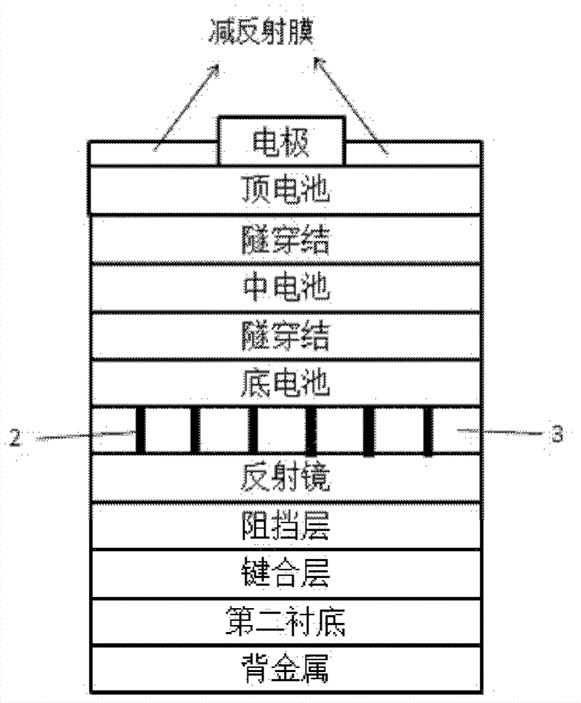
[0056] (3) On the basis of step (2), the current channel pattern is photolithographically formed, the figure is a frame rectangle figure, and the current channel are...

Embodiment 2

[0069] Embodiment 2, a kind of double-junction GaInP / GaAs solar cell manufacturing method with metal reflector, the steps are as follows:

[0070] (1) The double-junction solar cell epitaxial wafer is grown by MOCVD method, and the epitaxial wafer structure is as follows Figure 4 As shown, the top cell GaInP is first grown on the first substrate GaAs, and then the bottom cell GaAs is grown; the band gap of the top cell is larger than that of the bottom cell.

[0071] (2) cleaning the solar cell epitaxial wafer in step (1), removing surface organic matter and dirt, and vapor-depositing an ohmic contact GeAu metal layer on the surface of the second cap layer with a thickness of 3000 angstroms.

[0072] (3) On the basis of step (2), the photoetching current channel pattern, the pattern is a back-shaped pattern, and the current channel area is 5%-20% of the battery area. After the current channel pattern is corroded, the etching solution uses hydrogen peroxide: ammonia water: Wa...


PUM

PropertyMeasurementUnit
Thicknessaaaaaaaaaa
Thicknessaaaaaaaaaa
Thicknessaaaaaaaaaa

Abstract

The invention relates to a multi-junction solar cell with a metal reflector and a preparation method thereof. According to the method, an Ohmic contact current channel with partial contact is manufactured on a multi-junction solar cell structure, a second cap layer in other areas is removed, and transparent conductive dielectric material and a vapor plating metal reflector, a barrier metal layer and a bonding metal are manufactured in order. The bonding technology is employed, an epitaxial wafer is bonded to a second substrate, the epitaxial wafer with the removal of a first substrate is subjected to electrode vapor plating, an electrode pattern is formed through photoengraving, at the same time, a superfluous second cap layer is removed and then the alloying is carried out, an antireflection film is subjected to vapor plating, an electrode pattern is formed through photoengraving, a back side metal is subjected to vapor plating, and the alloying is carried out. According to the cell and the method, in the process of bonding, the metal reflector is prepared, the cap layer which adsorbs light heavily is removed, extra light is reflected back to the cell, the light utilization rate is improved, and the efficiency of the cell is improved.

Description

technical field [0001] The invention relates to photovoltaic power generation equipment utilizing solar energy, in particular to a method for preparing a multi-junction solar cell with metal reflectors, and belongs to the technical field of solar photovoltaic technology. Background technique [0002] Along with the energy crisis that people pay more and more attention to, the utilization of renewable energy has become the focus of people's attention and research. The photovoltaic technology developed based on this is more and more applied to people's daily life, and has joined the competition with petroleum power generation. In recent years, with the development of MOCVD technology, III-V solar cells, such as GaAs, GaInP and their multi-junction solar cells, have replaced traditional Si solar cells and applied to space vehicle energy systems, and the technology is becoming more and more mature, and the cost is getting higher and higher. Lower and lower, battery efficiency c...

Claims


Application Information

Patent Timeline
IPC IPC(8): H01L31/0216H01L31/18
CPCY02P70/50
Inventor 陈康夏伟于军张新
Owner JIANGSU YONGDING COMM
Why Eureka
Try Eureka