
Multi-state double-wire electrical arc welding device and welding method

An arc welding method and arc welding technology, applied in arc welding equipment, welding equipment, manufacturing tools, etc., can solve the problems of reducing welding heat input, etc., and achieve reducing welding heat input, increasing welding wire deposition rate, and low welding heat input Effect

Active Publication Date: 2013-10-09
HARBIN INST OF TECH
View PDF5 Cites 16 Cited by
  • Summary
  • Abstract
  • Description
  • Claims
  • Application Information

AI Technical Summary

Problems solved by technology

[0004] The present invention aims to solve the problem that there is a contradiction between increasing the welding wire deposition rate and reducing the welding heat input due to the fixed proportional relationship between the welding wire deposition rate and the welding heat input in the existing arc welding method, and provides a Multi-state twin-wire arc welding device and welding method

Method used


Image

  • Multi-state double-wire electrical arc welding device and welding method
  • Multi-state double-wire electrical arc welding device and welding method
  • Multi-state double-wire electrical arc welding device and welding method

Examples


specific Embodiment approach 1

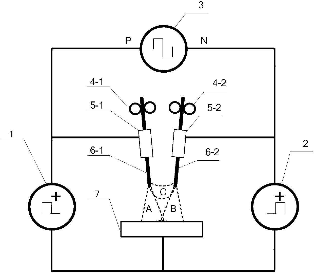
[0031] Specific implementation mode one: the following combination figure 1 Describe this embodiment, the multi-state twin-wire arc welding device described in this embodiment includes a first DC pulse power supply 1, a second DC pulse power supply 2, a variable polarity welding power supply 3, a first wire feeding mechanism 4- 1. The second wire feeding mechanism 4-2, the first contact tip 5-1, the second contact tip 5-2, the first welding wire 6-1 and the second welding wire 6-2,

[0032] The positive pole of the first DC pulse power supply 1 is connected to the P pole of the variable polarity welding power supply 3, the N pole of the variable polarity welding power supply 3 is connected to the positive pole of the second DC pulse power supply 2, and the negative pole of the second DC pulse power supply 2 is connected to The negative pole of the first DC pulse power supply 1 is connected to the center of a side of the workpiece 7 to be welded, and the side of the workpiece 7...

specific Embodiment approach 2

[0036]Specific Embodiment 2: This embodiment will further explain Embodiment 1. The first DC pulse power supply 1 and the second DC pulse power supply 2 in this embodiment are both DC pulse power supplies. The first DC pulse power supply 1 and the second DC pulse power supply Both the DC pulse power supply 2 and the variable polarity welding power supply 3 have constant current output characteristics, constant voltage output characteristics and high resistance output characteristics.

specific Embodiment approach 3

[0037] Specific implementation mode three: the following combination Figure 1 to Figure 4 Describe this embodiment, this embodiment is the multi-state twin-wire arc welding method based on the multi-state twin-wire arc welding device described in one of the above embodiments, which includes the following two stages:

[0038] The first stage:

[0039] Make the first DC pulse power supply 1 a constant voltage output, the second DC pulse power supply 2 a high-impedance output, the P pole of the variable polarity welding power supply 3 is positive, and the N pole is negative. At this time, the first DC pulse power supply 1 A left main arc A is formed between the first welding wire 6-1 and the workpiece 7 to be welded; the variable polarity welding power supply 3 forms an indirect arc C between the ends of the first welding wire 6-1 and the second welding wire 6-2; Then the current flowing through the first welding wire 6-1 is the sum of the current I1 produced by the first DC pu...


PUM


Abstract

The invention provides a multi-state double-wire electrical arc welding device and welding method to solve the problem that in an existing electrical arc welding method, due to the fact that a fixed proportional relationship exists between the welding wire deposition rate and the weld heat input, contradictions exist between welding wire deposition rate increase and weld heat input reduction, and belongs to the technical field of consumable electrode electrical arc welding. The device comprises a first direct-current pulse power supply, a second direct-current pulse power supply, a welding power supply with the alterable polarity, a first wire sending mechanism, a second wire sending mechanism, a first contact tube, a second contact tube, a first welding wire and a second welding wire. In the welding process, the first direct-current pulse power supply, the first welding wire and a workpiece to be welded form a left electrical arc welding circuit, the second direct-current pulse power supply, the second welding wire and the workpiece to be welded form a right electrical arc welding circuit, and the welding power supply with the alterable polarity, the first welding wire and the second welding wire form a shunt circuit. The multi-state double-wire electrical arc welding device and welding method are used for electrical arc welding.

Description

technical field [0001] The invention relates to a multi-state twin-wire arc welding device and a welding method, belonging to the technical field of melting electrode arc welding. Background technique [0002] In order to improve welding efficiency, metal arc welding has become the preferred method. For metal arc welding, the welding efficiency mainly depends on the deposition rate of the welding wire, that is, the melting amount of the welding wire per unit time. Therefore, the key to improving the welding efficiency is to increase the deposition rate of the welding wire. [0003] In order to greatly improve the welding efficiency of metal arc welding, the use of twin-wire arc welding is undoubtedly the most effective technical means. The twin-wire welding method can not only effectively increase the welding wire deposition rate, but also provide more technical means for controlling the welding heat input. At present, due to the widespread use of high-strength steels that...

Claims


Application Information

Patent Timeline
Patent Type & Authority Applications(China)
IPC IPC(8): B23K9/00B23K9/09
Inventor 耿正
Owner HARBIN INST OF TECH
Learn More