Super-precision directly driving static pressure main shaft dynamic balance method

A hydrostatic spindle and ultra-precision technology, which is applied in the field of dynamic balance of ultra-precision hydrostatic spindle, can solve the problem of inability to achieve precise dynamic balance of the rotor of ultra-precision hydrostatic spindle, achieve accurate and reliable dynamic balance results, eliminate influences, and methods. Simple and easy effects

Active Publication Date: 2013-10-02
HARBIN INST OF TECH
View PDF3 Cites 3 Cited by
  • Summary
  • Abstract
  • Description
  • Claims
  • Application Information

AI Technical Summary

Problems solved by technology

[0003] The purpose of the present invention is to solve the problem that the existing method cannot realize the precise dynamic balance of the ultra-precision static pressure spindle rotor, and provides an ultra-precision direct-drive static pressure spindle rotor dynamic balance method

Method used


Image

  • Super-precision directly driving static pressure main shaft dynamic balance method

Examples


specific Embodiment approach 1

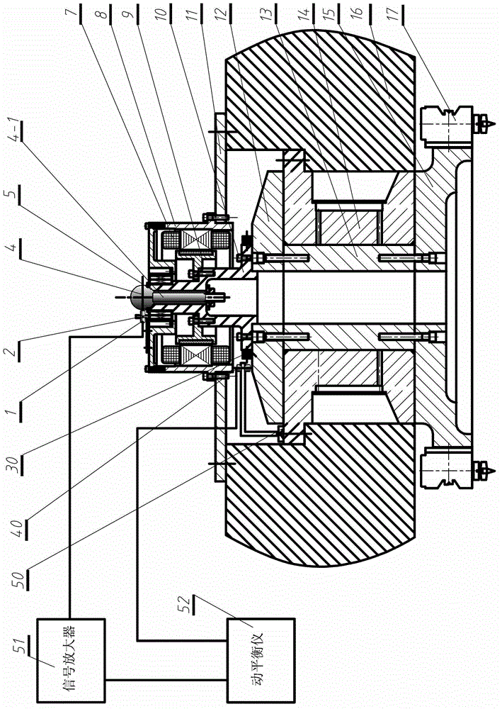
[0010] Specific implementation mode one: combine figure 1 Describe this embodiment, the online testing method described in this embodiment is based on including a vertical ultra-precision direct-drive hydrostatic spindle system, a measurement system, and a dynamic balancer 52;

[0011] The vertical ultra-precision direct-drive hydrostatic spindle system includes a servo motor, an ultra-precision direct-drive hydrostatic spindle (rotating part, namely the rotor part), a machine tool beam support plate (machine tool beam cover plate) 11, a spindle bushing 14 (stator Part), machine tool beam 16 and micro-feed tool rest 17; ultra-precision direct-drive hydrostatic spindle rotor consists of input end part 10, upper thrust plate 12, shaft center 13, bottom stop The push plate 15 is fixedly connected; the servo motor includes a motor stator 7, a motor rotor 9 and a casing 8; the dynamic balance source signal measurement system consists of a measurement reference ball 4 installed at t...

specific Embodiment approach 2

[0014] Specific implementation mode two: combination figure 1 To illustrate this embodiment, the specific implementation process of the dynamic balancing method is as follows: Step 1, install the measurement reference: install the standard ball 4 on the upper end of the detection rod 4-1 on the input end part 10 of the ultra-precision direct-drive static pressure spindle In the tapered installation datum plane 5 processed on the end face, the lower end of the detection rod 4-1 is fixed inside the hollow input end part 10 through a nut; Step 2, install the high-precision displacement sensor 1 and the photoelectric speedometer 40: first, place the high-precision displacement sensor The sensor bracket 2 is fixed on the casing of the motor stator, and then the high-precision displacement sensor 1 is installed through the mounting hole on the bracket 2, and the photoelectric speedometer 40 is installed on the speedometer bracket 50 at the same time, and the speedometer bracket 50 is...

specific Embodiment approach 3

[0016] Specific implementation mode three: combination figure 1 To illustrate this embodiment, the standard ball of this embodiment is ground and polished, and the material is special stainless steel. After polishing, the PV value of the surface shape accuracy is better than λ / 20 (wherein λ=0.633 μm), and the surface roughness is better than 2nm. Other compositions and connections are the same as those in Embodiment 1 or Embodiment 2.


PUM

PropertyMeasurementUnit
Surface roughnessaaaaaaaaaa

Abstract

A super-precision directly driving static pressure main shaft dynamic balance method relates to a static pressure main shaft dynamic balance method, which aims to solve the problem that the conventional method cannot realize the precise dynamic balance of a super-precision static pressure main shaft rotor. A conical mounting reference surface is processed at the rear end of the directly driving super-precision static pressure main shaft rotor; a standard ball is directly mounted on the conical reference surface and services as a measurement reference; the change of displacement of the standard ball and the high-precision displacement sensor is measured by adopting a high-precision displacement sensor when a main shaft is in rotation; the change is amplified into a 0-10 V signal via a sensor signal amplifier, which is input to a dynamic balancing instrument; information about the rotation speed of the main shaft, measured by a photoelectric velocimeter, is input into the dynamic balancing instrument; the measured information is processed by the dynamic balancing instrument to obtain the imbalance mass and the phase of the rotor; a required balancing weighting block is added on a dynamic balancing disc according to the indicated phase of the dynamic balancing instrument. The rotation center of the main shaft surely and well overlaps with the rotation center of a measurement reference ball, and influence of a mounting error on the measurement result is eliminated.

Description

technical field [0001] The invention relates to an ultra-precise static pressure spindle dynamic balancing method. Background technique [0002] With the rapid development of modern science and technology, especially the rapid advancement of cutting-edge science and technology such as aviation, aerospace, national defense, and military industry, these industries have higher and higher requirements for product stability and performance. The typical example is laser nuclear fusion. The KDP crystal device is widely used in the system. Due to the characteristics of the crystal such as soft, brittle, and easy to deliquescence, traditional optical processing methods such as grinding and polishing cannot be used for processing large-diameter KDP crystals. The main means of crystal final processing. Cutting processing is a kind of copy processing, and the precision of ultra-precision machine tools determines the processing accuracy of parts. Therefore, the ultra-precision machinin...

Claims


Application Information

Patent Timeline
IPC IPC(8): G01M1/14
Inventor 张勇付鹏强张飞虎梁迎春张强张龙江
Owner HARBIN INST OF TECH
Why Eureka
Try Eureka