
Charge-discharge equalization control circuit of battery pack

A charge-discharge circuit and balanced control technology, which is applied to battery circuit devices, circuit devices, collectors, etc., can solve problems such as battery consistency damage, battery overcharging, and battery capacity reduction.

Active Publication Date: 2015-06-17
STATE GRID CORP OF CHINA +3
View PDF6 Cites 0 Cited by
  • Summary
  • Abstract
  • Description
  • Claims
  • Application Information

AI Technical Summary

Problems solved by technology

[0003] However, when the lithium iron phosphate battery is charged and discharged at a high rate, the actual specific capacity is low. Therefore, although the lithium iron phosphate battery has the above-mentioned advantages, it is used in the field of backup power, especially in the field of backup power for substations. Obviously, shallow charging and shallow discharging of lithium iron phosphate batteries cannot be effectively performed, and high-rate charging and discharging are prone to occur, so that the physical and chemical characteristics of lithium iron phosphate batteries cannot be effectively maintained.
[0004] When the physical and chemical properties of a certain battery change, there will be differences between the individual batteries in the battery pack, which will lead to over-discharge of some batteries in the long run
The same is true during the charging process. If you do not consider the difference between the battery cells and charge them, it may lead to overcharging of a single battery.
If a single battery is over-discharged or overcharged for a long time, its battery capacity will be reduced, its service life will be shortened, and the consistency of the entire battery pack will be destroyed, thereby shortening the battery pack's life.

Method used


Image

  • Charge-discharge equalization control circuit of battery pack
  • Charge-discharge equalization control circuit of battery pack
  • Charge-discharge equalization control circuit of battery pack

Examples


Embodiment 1

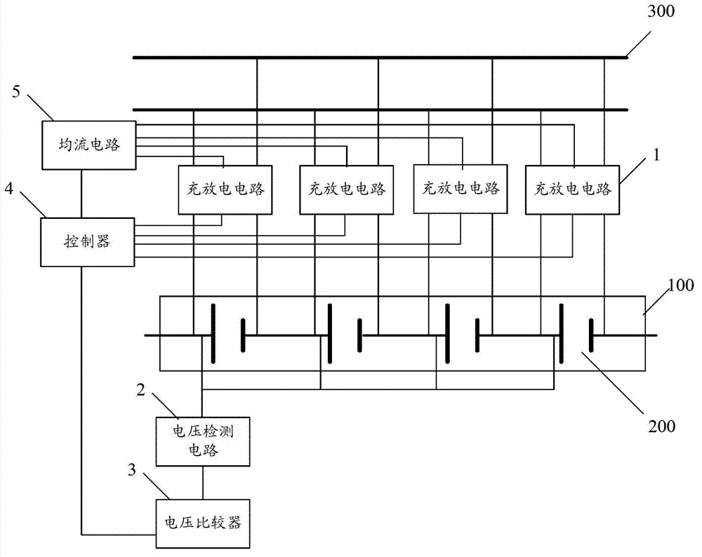
[0049] figure 1 It is a schematic structural diagram of a charge-discharge balance control circuit for a battery pack provided in an embodiment of the present application.

[0050] The control circuit is used to control the charging process of the battery pack, so that the battery cells in the battery pack can achieve balanced charging, and for the battery pack, at least two battery cells are included. figure 1 Among them, 100 is a battery pack, 200 is a battery cell, and 300 is a power cord for charging the battery pack.

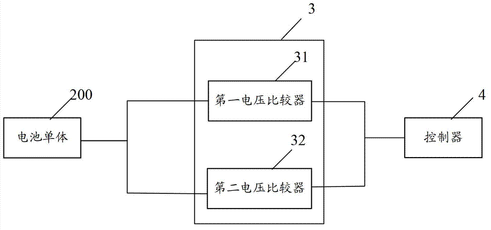
[0051] Such as figure 1 As shown, the control circuit includes: a charging and discharging circuit 1, a voltage detection circuit 2, a voltage comparator 3, a controller 4, a current equalizing circuit 5 and a discharge switch (not shown in the figure).

[0052] The input terminal of the charging and discharging circuit 1 is connected to the power line 300, and the output terminals of the charging and discharging circuit 1 are respectively connected to at...

Embodiment 2

[0084] In order to avoid energy loss caused by frequent detection of the battery cell voltage, in other embodiments of the present application, the interval time of detection can also be set during the charging process of different modes.

[0085] Figure 5 A schematic structural diagram of another charging and discharging equalization control circuit for a battery pack provided in an embodiment of the present application.

[0086] Such as Figure 5 As shown, the charge-discharge equalization control circuit may further include: a delay controller 6, and the delay controller 4 is connected to the voltage detection circuit 2 for controlling the detection interval of the voltage detection circuit.

[0087] When the average voltage is less than the first preset voltage threshold and the charging current is between 0.1C and 0.2C, a first delay instruction is generated and sent to the voltage detection circuit to control the voltage detection circuit 2 to delay the first preset A...

Embodiment 3

[0093] In the first embodiment above, it is possible to adjust the charging condition of the battery cell with a faster charging speed, but after the adjustment is completed, the charging condition of the battery cell will tend to be normal. , will again cause this cell to charge slower than the other cells.

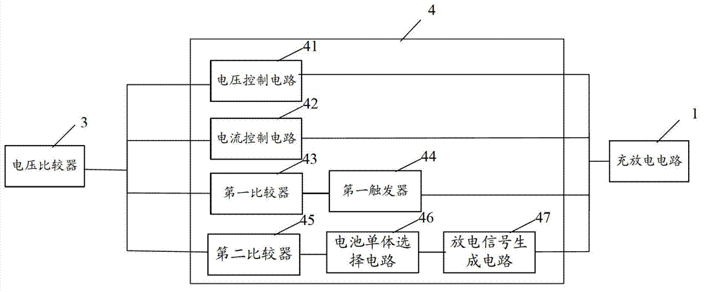
[0094] For this reason, in the embodiment of this application, such as Image 6 As shown, the controller 4 in the control circuit may also include: a third comparator 49 and a third flip-flop 50, wherein:

[0095] The third comparator 49 is connected with the voltage comparator 3, and is used for judging whether the voltage difference of the battery cells in the battery pack is less than a preset threshold, where the preset threshold takes into account the difference between the cells The difference is set, that is, the small difference between the battery cells is allowed;

[0096] The third flip-flop 50 is connected with the third comparator 49, and is used to genera...


PUM


Abstract

The invention discloses a charge-discharge equalization control circuit of a battery pack. The charge-discharge equalization control circuit comprises a charge-discharge circuit, a voltage detection circuit, a voltage comparator, a controller, a current-sharing circuit and a discharge switch. An input end of the charge-discharge circuit is connected with a power line, and an output end of the charge-discharge circuit is connected with at least two battery single bodies respectively. An input end of the voltage detection circuit is connected with at least two battery single bodies respectively. An input end of the voltage comparator is connected with an output end of the voltage detection circuit. An input end of the controller is connected with the voltage comparator, and an output end of the controller is connected with the charge-discharge circuit. The current-sharing circuit is connected with the charge-discharge circuit and the controller. The discharge switch is located in the charge-discharge circuit. The charge-discharge equalization control circuit can ensure charging equalization between the battery single bodies through a replacing mode and a current-sharing mode in the charging process, can control the high-voltage battery single bodies to charge the low-voltage battery single bodies, and further ensures the mutual equalization between the battery single bodies in the discharging process.

Description

technical field [0001] The present application relates to the technical field of battery pack control, in particular to a battery pack charge and discharge equalization control circuit. Background technique [0002] Lithium iron phosphate battery is a new type of secondary power supply newly developed in recent years. Its main advantages are large input and output power, wide operating temperature range, no memory effect, long life of more than 2000 times, green environmental protection and floating charge characteristics. Outstanding features, widely used in the field of electric vehicles and energy storage power stations. [0003] However, when the lithium iron phosphate battery is charged and discharged at a high rate, the actual specific capacity is low. Therefore, although the lithium iron phosphate battery has the above-mentioned advantages, it is used in the field of backup power, especially in the field of backup power for substations. Obviously, shallow charging an...

Claims


Application Information

Patent Timeline
Patent Type & Authority Patents(China)
IPC IPC(8): H02J7/00
Inventor 吴哲杨磊曹辉郑昌庭陈建胜刘主光李勇蔡步奖张磊万晓倪相生林高翔陈达民叶立兆雷欢林琳周耀庭董孜孜金林
Owner STATE GRID CORP OF CHINA
Learn More