Novel electromagnetic pump

An electromagnetic pump, a new type of technology, applied in the field of electromagnetic pumps, can solve the problems of tension spring processing difficulties, high scrap rate, and consumption of processing time, and achieve simple and convenient production and assembly processes, good product consistency, and improved consistency Effect

Inactive Publication Date: 2013-09-04
王荐品
View PDF4 Cites 0 Cited by
  • Summary
  • Abstract
  • Description
  • Claims
  • Application Information

AI Technical Summary

Problems solved by technology

Traditional electromagnetic pumps use a hollow piston rod, and then use a plug and a spring or extension spring at the front end of the piston rod to form a water inlet check valve. However, the piston rod is a slender piece and is made of soft magnetic material. It is very difficult to drill a slender hole in the center, which consumes a lot of processing time; the one-way valve formed by the plug at the front end of the piston rod and the spring has a large range of motion, which is easy to cause noise. The plug seal of the directional valve is not very reliable, so that the working pressure of the whole electromagnetic pump can be reduced; some one-way valves with a tension spring structure are prone to wear and tear due to the tension spring in the small hole inside the piston rod and its frequent up and down movements. , the processing of the extension spring is also difficult and complicated, and the assembly is also very troublesome
There are also some electromagnetic pumps that use injection molding to manufacture piston rods, but because the piston rods are thin and long, there must be holes in the middle that can provide sufficient flow of water to pass through, so that the wall thickness of the piston rods is extremely thin, which affects the injection molding process and material selection of plastics. It brings great difficulties and also makes the scrap rate during manufacturing remain high

Method used


Image

  • Novel electromagnetic pump
  • Novel electromagnetic pump
  • Novel electromagnetic pump

Examples


Embodiment Construction

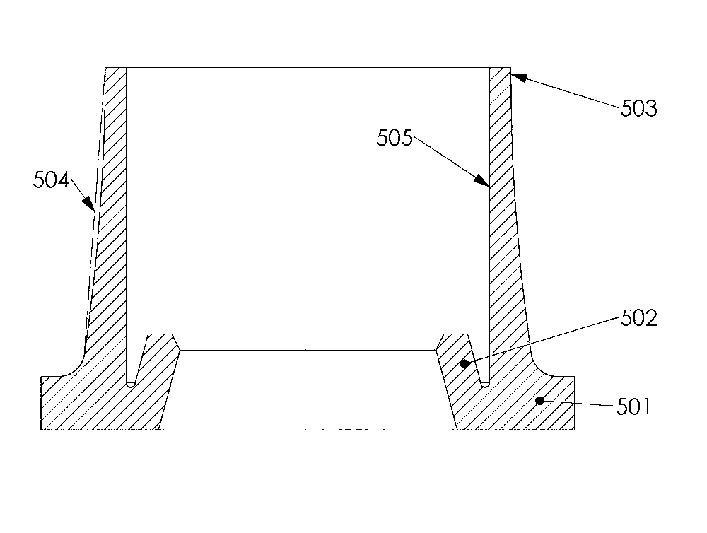
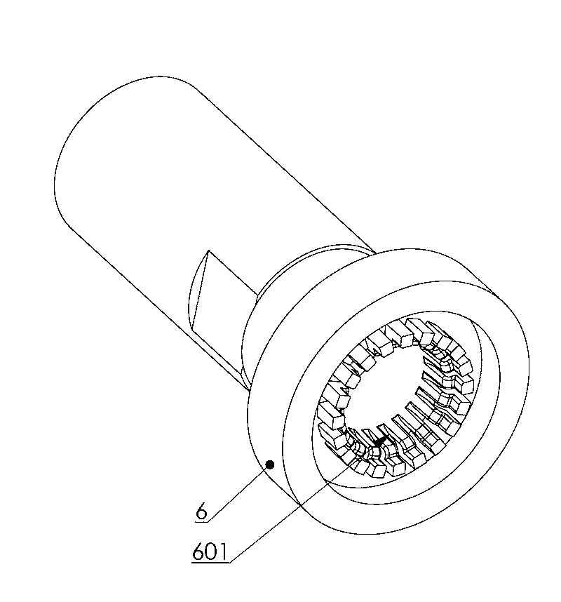
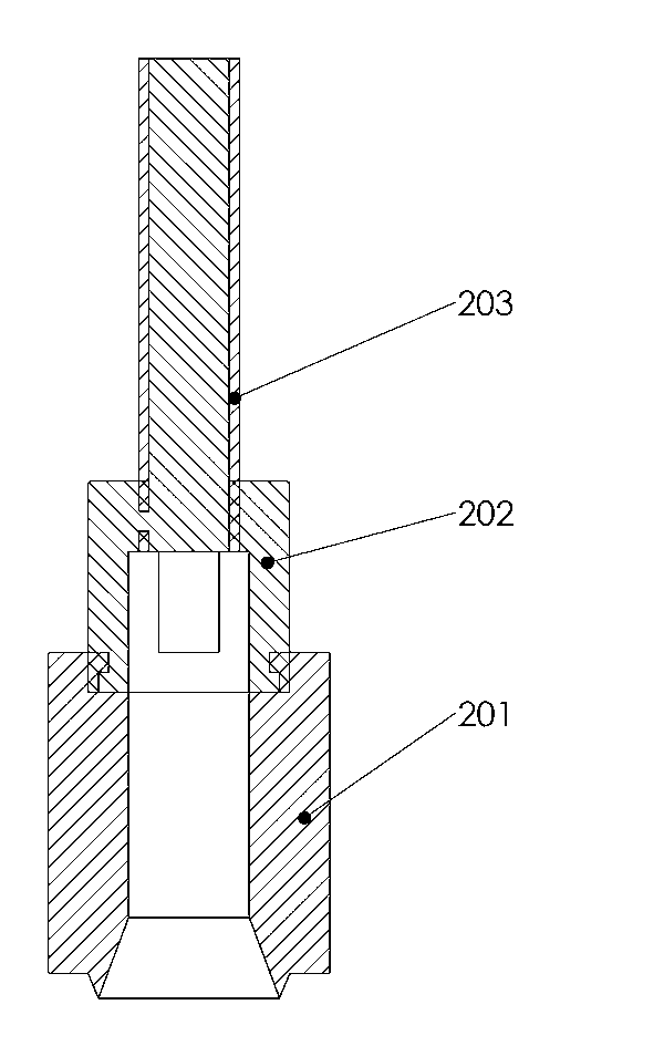
[0025] The technical solution of the present invention will be further described through the following examples in conjunction with the accompanying drawings: a new electromagnetic pump, including a coil assembly 1, a piston assembly 2, a water inlet pipe 3, a positioning sleeve 4, a one-way valve seal 5, and a water outlet 6 , the water outlet check valve 7 and the front and rear springs 8, 9, the coil assembly 1, the water inlet pipe 3, the water outlet check valve 7 and the front and rear springs 8, 9 are manufactured by known public technology, and the slender piston rod 202 part of the piston assembly 2 is Solid, the one-way valve seal 5 of this embodiment is made of rubber material, and its structure is composed of a body 501, an axial sealing part 502, a one-way sealing part 503, a water inlet pressure part 504 and an inner cavity 505:

[0026] Body 501: It is the basic part of the one-way valve seal 5, extending upward is the water inlet pressure part 504, and the insid...


PUM


Abstract

A novel electromagnetic pump comprises a coil assembly, a piston assembly, a water inlet pipe, a positioning sleeve, a one-way valve sealing element, a water outlet, a water outlet one-way valve, a front spring and a rear spring. The novel electromagnetic pump is characterized in that a long and thin piston rod of the piston assembly is solid, and the one-way valve sealing element is made of an elastic material such as rubber and polyurethane and structurally comprises a body, an axial sealing portion, a one-way sealing portion, a water inlet pressure portion and an inner cavity. The novel electromagnetic pump has the advantages that a one-way plug and a one-way valve spring which are required when an existing electromagnetic valve is manufactured in the prior art are omitted, the one-way valve sealing element replaces an original axial sealing element, and an axial sealing function and functions of a water inlet one-way valve are integrated; the solid piston rod is utilized, small holes are not required to be perforated in the middle of the long and thin piston rod, accordingly, the structure of the electromagnetic pump is greatly improved, and manufacture and assembly processes are simplified and facilitated; running noise of the integral electromagnetic pump further can be reduced, and the consistency of the working performance of the electromagnetic pump further can be improved.

Description

technical field [0001] The invention relates to an electromagnetic pump using water as a fluid, in particular to an electromagnetic pump used in the field of small household appliances. Background technique [0002] Electromagnetic pumps are widely used in the field of small household appliances, especially in the water supply systems of coffee machines, electric irons and water dispensers. Traditional electromagnetic pumps use a hollow piston rod, and then use a plug and a spring or extension spring at the front end of the piston rod to form a water inlet check valve. However, the piston rod is a slender piece and is made of soft magnetic material. It is very difficult to drill a slender hole in the center, which consumes a lot of processing time; the one-way valve formed by the plug at the front end of the piston rod and the spring has a large range of motion, which is easy to cause noise. The plug seal of the directional valve is not very reliable, so that the working pr...

Claims


Application Information

Patent Timeline
Patent Type & Authority Applications(China)
IPC IPC(8): F04B53/14F04B53/00F04B17/04
Inventor 黄红良
Owner 王荐品
Why Eureka
Try Eureka