
Integrated type energy-saving and environment-friendly hydraulic servo system

A hydraulic servo system, energy saving and environmental protection technology, applied in fluid pressure actuation system components, presses, fluid pressure actuation devices, etc., can solve the problems of increased oil leakage and failure, energy consumption, and large space occupation , to achieve the effect of improving work efficiency, reducing loss along the way, and occupying less space

Inactive Publication Date: 2013-08-28
NORTHEASTERN UNIV
View PDF6 Cites 12 Cited by
  • Summary
  • Abstract
  • Description
  • Claims
  • Application Information

AI Technical Summary

Problems solved by technology

[0003] 1. The proportional servo valve consumes a certain amount of energy when controlling, and the along-course loss, local loss and leakage loss in the process of oil flow will lead to low transmission efficiency;
[0004] 2. Proportional servo valves require relatively high manufacturing precision, which brings certain difficulties to use and maintenance, and the cost is also relatively high;
[0006] 4. The proportional servo system will generate relatively large noise, which will have a certain impact on the operator. Although the ultra-quiet transformation can be carried out now, it has not fundamentally solved the problem;
[0007] 5. The entire hydraulic system, from the oil tank to the actuator, occupies a relatively large space, and a lot of connecting pipelines are needed in the middle, which increases the chance of oil leakage and failure

Method used


Image

  • Integrated type energy-saving and environment-friendly hydraulic servo system
  • Integrated type energy-saving and environment-friendly hydraulic servo system
  • Integrated type energy-saving and environment-friendly hydraulic servo system

Examples


Embodiment

[0030] The invention is applied to a powder alloy press forming hydraulic press.

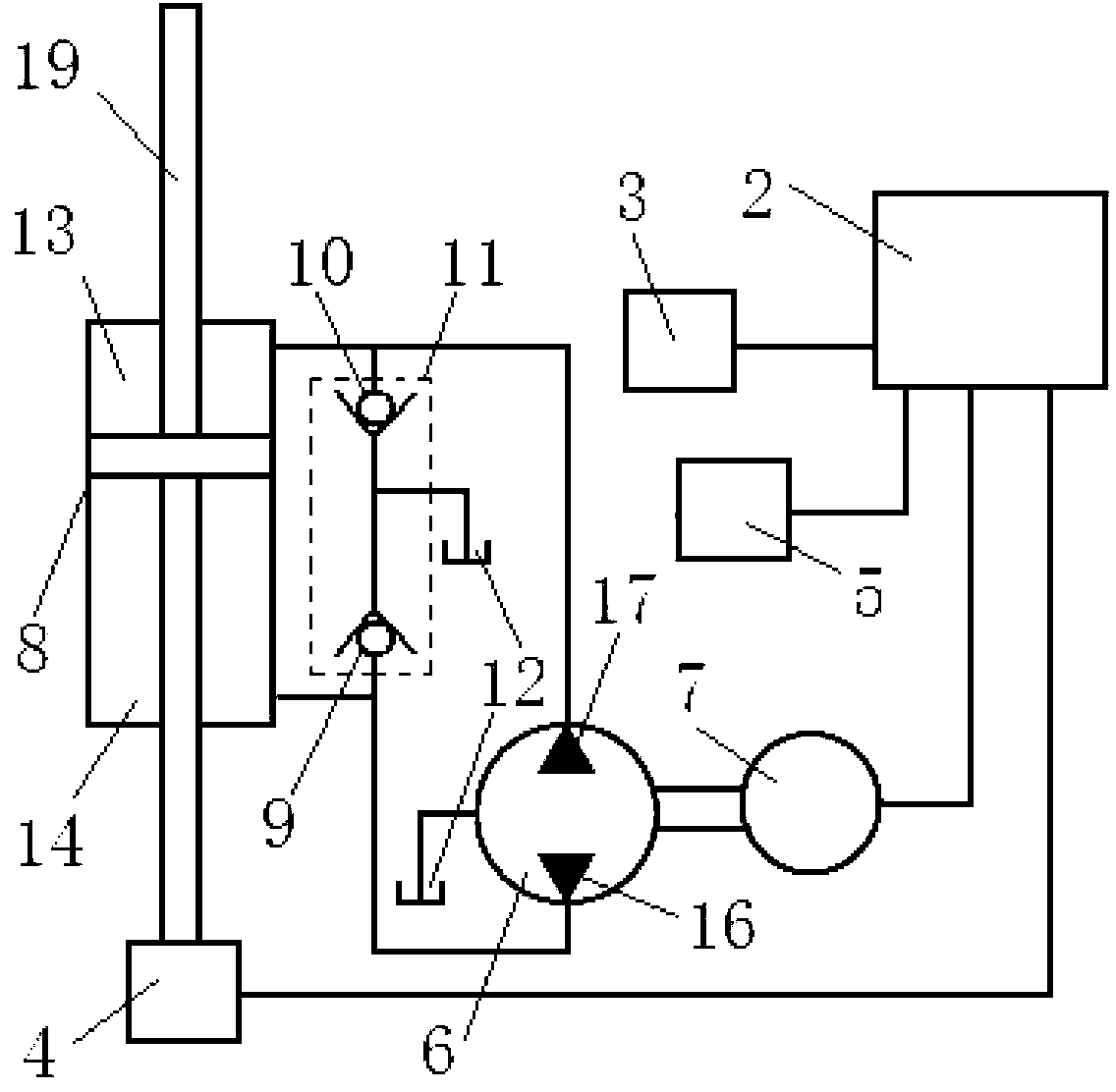
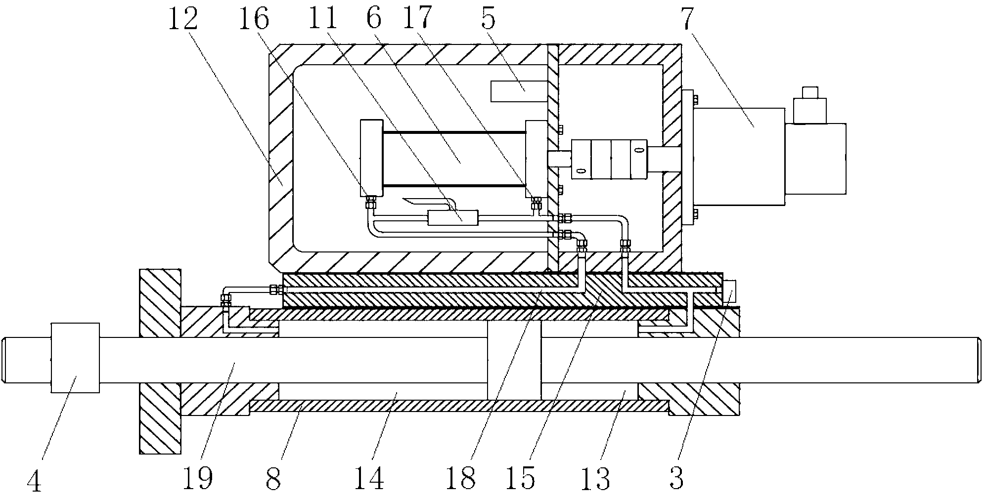
[0031] In this embodiment, the hydraulic pump 6 of the power output control part adopts the model Taisheng SNBY16 / 1.6 two-way gear oil pump, the servo motor 7 adopts the model of Beijing Senchuang 130MB series AC servo motor, and the pressure sensor 3 adopts the model of Beijing Zhengkai Instrument Co., Ltd. The company's MCY-B1 stainless steel pressure sensor (range 0 ~ 20Mpa), the force sensor 4 adopts the MCL-S2 tension pressure sensor (range 0 ~ 100kN) of Beijing Zhengkai Instrument Co., Ltd., and the temperature sensor 5 adopts the model It is a TE-80 digital display temperature sensor (range -50-200°C) of BANNA Company in the United States.

[0032] Make the powder alloy pressing and forming hydraulic machine energized, the computer 2 of the present invention starts, and it can be seen by the computer 2 that the rotating speed of the servo motor 7 is zero at this time, the initial values ​...


PUM


Abstract

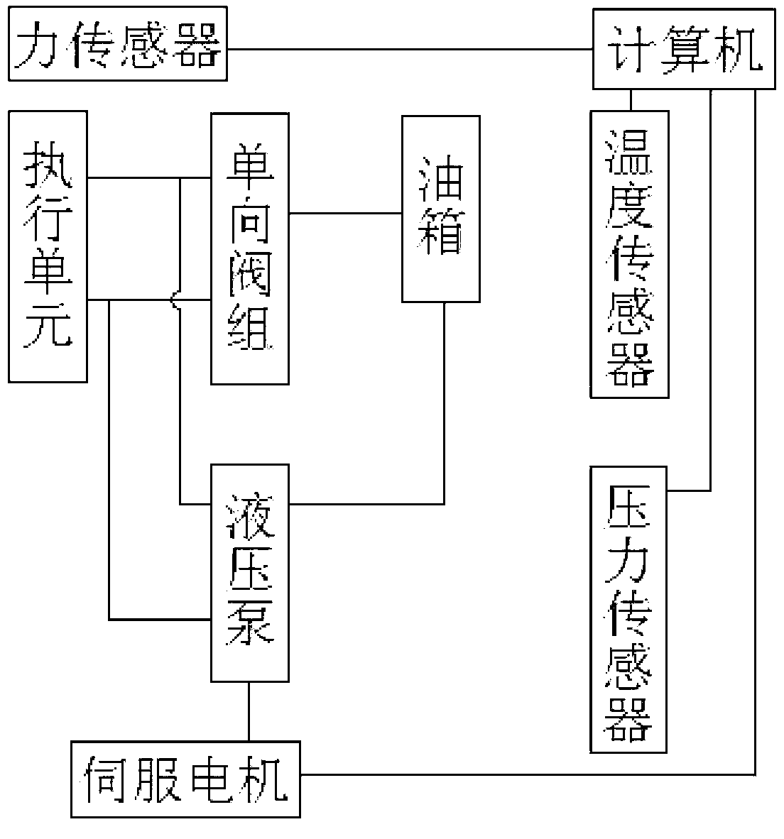
The invention discloses an integrated type energy-saving and environment-friendly hydraulic servo system, and belongs to the technical field of machinery assemblies. The integrated type energy-saving and environment-friendly hydraulic servo system comprises a computer, a data collecting part, a power output control part, a one-way valve set, a connecting block and an executing unit. The data collecting part comprises a force sensor, a pressure sensor and a temperature sensor. The power output control part comprises a hydraulic pump, a servo motor and an oil tank. The one-way valve set comprises a first one-way valve and a second one-way valve. An oil channel is placed inside the connecting block. A hydraulic cylinder is adopted in the executing unit, and is composed of a pressurizing cavity, a pressure releasing unit and a piston rod. The computer is connected with the force sensor, the pressure sensor and the temperature sensor. The servo motor is connected with the computer and the hydraulic pump, the hydraulic pump is installed inside the oil tank, and the servo motor is installed outside the oil tank. The oil tank is fixedly connected with a hydraulic cylinder body through the connecting block in a sealing mode, the hydraulic pump is communicated with the hydraulic cylinder through the connecting block, the oil inlet ends of the one-way valves are communicated with the oil tank, and the oil outlets of the one-way valves are communicated with the hydraulic pump.

Description

technical field [0001] The invention belongs to the technical field of mechanical components, in particular to an integrated energy-saving and environment-friendly hydraulic servo system. Background technique [0002] At present, the application of hydraulic systems is becoming more and more extensive, the application environment is becoming more and more complex, and the corresponding application requirements and performance requirements are also getting higher and higher. For example, for the necessary equipment for the research of new materials - the vacuum thermoforming machine, for the performance of the hydraulic system in it, it is required to be able to achieve precise control of different pressure levels. For the traditional pressure precise control of the hydraulic system, it is generally controlled by a proportional servo valve, but this control method will change with the change of temperature and time, which is a difficult point for the design of the control sys...

Claims


Application Information

Patent Timeline
Patent Type & Authority Applications(China)
IPC IPC(8): B30B15/22F15B21/08
Inventor 周生浩宋锦春
Owner NORTHEASTERN UNIV
Learn More