
Inductive element and manufacturing method thereof

A technology of inductive components and components, applied in the manufacture of inductors/transformers/magnets, electrical components, transformers/inductor cores, etc., can solve problems such as volume reduction

Active Publication Date: 2013-08-14
SICHUAN HUASEN XINKE INFORMATION CO LTD
View PDF6 Cites 4 Cited by
  • Summary
  • Abstract
  • Description
  • Claims
  • Application Information

AI Technical Summary

Problems solved by technology

However, for the in-between situation, that is, the inductor element with large inductance value and small size, it has not been covered.
This is because the stacking lamination and printing process of multilayer chip inductors limit the improvement of the inductance value of this type of inductor, while the manufacturing process of wire wound chip inductors limits its performance at an acceptable cost. to further reduce its volume

Method used


Image

  • Inductive element and manufacturing method thereof
  • Inductive element and manufacturing method thereof
  • Inductive element and manufacturing method thereof

Examples


Embodiment Construction

[0098] The invention discloses a laminated inductive element and a manufacturing method thereof. The laminated inductive element can be used to form inductors, antennas, common mode choke coils, transformers and the like.

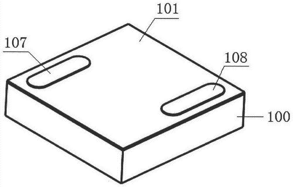
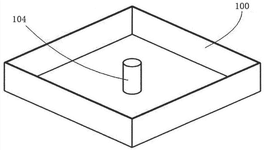
[0099] Figure 1 to Figure 5 is a diagram of an inductor of the first embodiment of the inductive element of the present invention. in, figure 1 is the general structure diagram of the inductor. Seen from the outside, the inductor is a box-shaped structure with a box body 100 and a box cover 101 , and the box cover 101 has two electrodes 107 and 108 . Wherein, the box body 100 and the box cover 101 can be combined to form a closed-circuit magnetic core used in this embodiment.

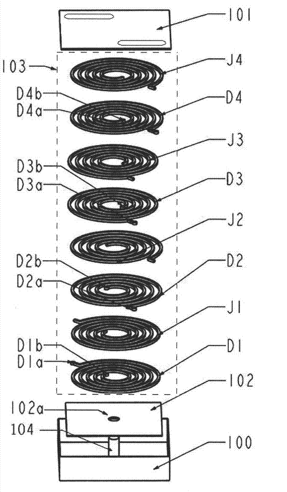
[0100] figure 2 An exploded view of the inductor of the first embodiment is given. The inductor includes a substrate 102, a laminated body 103, and a closed-circuit magnetic core. Wherein, the substrate 102 has a through hole 102a (see Figure 4 ), the central axis of the th...


PUM


Abstract

The invention discloses an inductive element and a manufacturing method thereof. The inductive element comprises laminated bodies and a closed-circuit magnetic core, each laminated body is formed by alternate laminating of a planer spiral coil and an insulation layer, a through hole is reserved at the center of each laminated body, the planer spiral coils encircle the through holes, and one part of the closed-circuit magnetic core penetrates through the through holes. Compared with a laminated inductor in the prior art, the inductive element has the advantages that size is increased slightly, and inductance is improved greatly.

Description

technical field [0001] The present invention relates to an inductive element and its manufacturing method, in particular to laminated inductive elements such as laminated power inductors, laminated common mode choke coils, high-frequency laminated inductors and magnetic beads, electronic transformers, and antennas, and their manufacturing methods. Background technique [0002] As one of the three major passive components, inductors are widely used in electronic systems. As electronic technology enters the era of miniaturization and high-density assembly, traditional through-hole plug-in wirewound inductors can no longer meet the requirements of light, thin, short and small modern electronic equipment. Therefore, in the 1970s and 1980s, chip inductors came into being and developed rapidly. At present, chip inductors mainly include two types: wire-wound chip inductors and laminated chip inductors. [0003] As explained in "Conference Proceedings of Soft Ferrite Materials and...

Claims


Application Information

Patent Timeline
IPC IPC(8): H01F41/00H01F27/30H01F27/24H01F3/00
Inventor 林华森汪阳袁德喜林晓利
Owner SICHUAN HUASEN XINKE INFORMATION CO LTD
Learn More