Method for building lubricating oil film model after thermal mechanical coupling deformation of hydrostatic thrust bearing

A technology of thermomechanical coupling and static pressure thrust, which is applied in special data processing applications, instruments, electrical digital data processing, etc., can solve the problems of workpiece efficiency and accuracy, and achieve the improvement of machine tool speed, safe operation avoidance, and avoidance of lubrication failure. Effect

Inactive Publication Date: 2013-08-14
HARBIN UNIV OF SCI & TECH
View PDF3 Cites 14 Cited by
  • Summary
  • Abstract
  • Description
  • Claims
  • Application Information

AI Technical Summary

Problems solved by technology

[0004] The present invention aims to solve the problem that the existing method of establishing an oil film model has a great influence on the efficiency and precision of the workpiece, and provides a method for establishing a lubricating oil film model of a hydrostatic thrust bearing after thermomechanical coupling deformation

Method used


Image

  • Method for building lubricating oil film model after thermal mechanical coupling deformation of hydrostatic thrust bearing
  • Method for building lubricating oil film model after thermal mechanical coupling deformation of hydrostatic thrust bearing
  • Method for building lubricating oil film model after thermal mechanical coupling deformation of hydrostatic thrust bearing

Examples


specific Embodiment approach 1

[0016] Specific Embodiment 1: In this embodiment, a method for establishing a lubricating oil film model after thermal coupling deformation of a hydrostatic thrust bearing is implemented in the following steps:

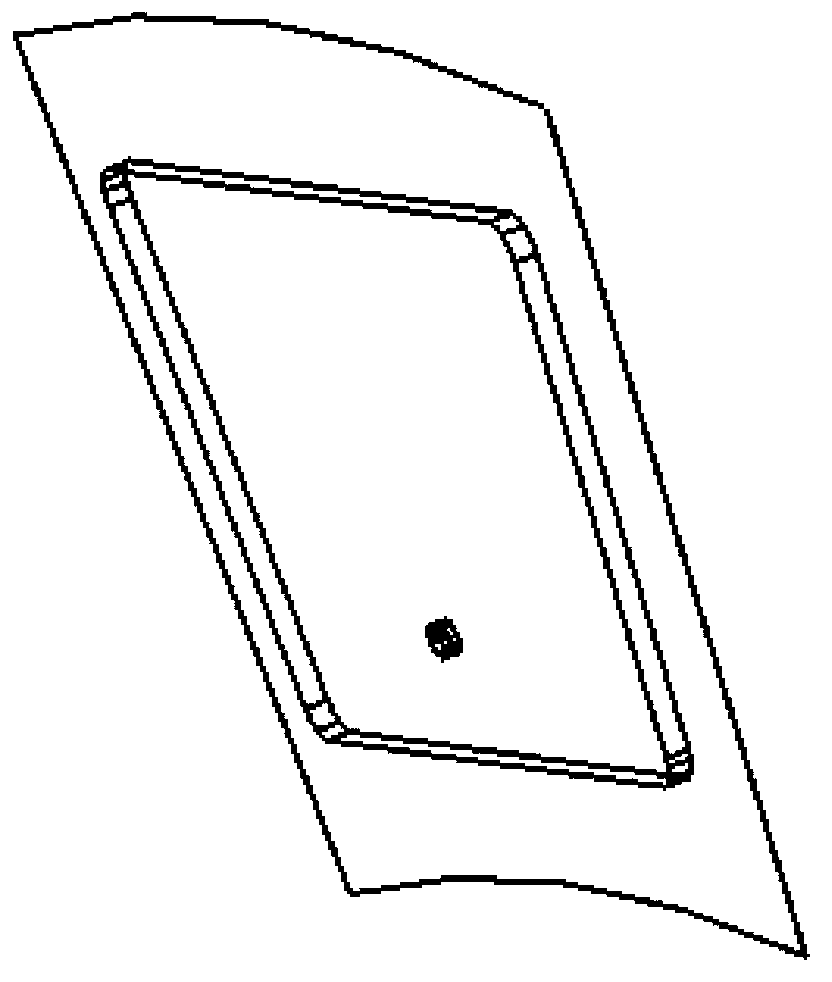
[0017] Step A. Based on the dimensional structure of the test machine tool and the given initial oil film thickness, use 3D modeling software to build models of the workbench, base, fan-shaped oil chamber and initial oil film, assemble the workbench, base and oil chamber, and export to zhuangpei .x_t and youmo.x_t files (where the workbench and base are 1 / 12 models);

[0018] Step B. Use GAMBITZ software to mesh the initial oil film to obtain a high-quality mesh, specify the boundary conditions of the fluid domain and output the youmo.fluent5 / 6mesh file, and import the youmo.fluent5 / 6mesh file into FLUENT to input or select the oil film inlet temperature T in Initial value, initial value of oil film fixed wall surface temperature, oil film inlet flow rate Q, outlet p...

specific Embodiment approach 2

[0024] Embodiment 2: This embodiment differs from Embodiment 1 in that: in step A, the workbench and the base are analyzed using a 1 / 12 model. Other steps and parameters are the same as those in Embodiment 1.

specific Embodiment approach 3

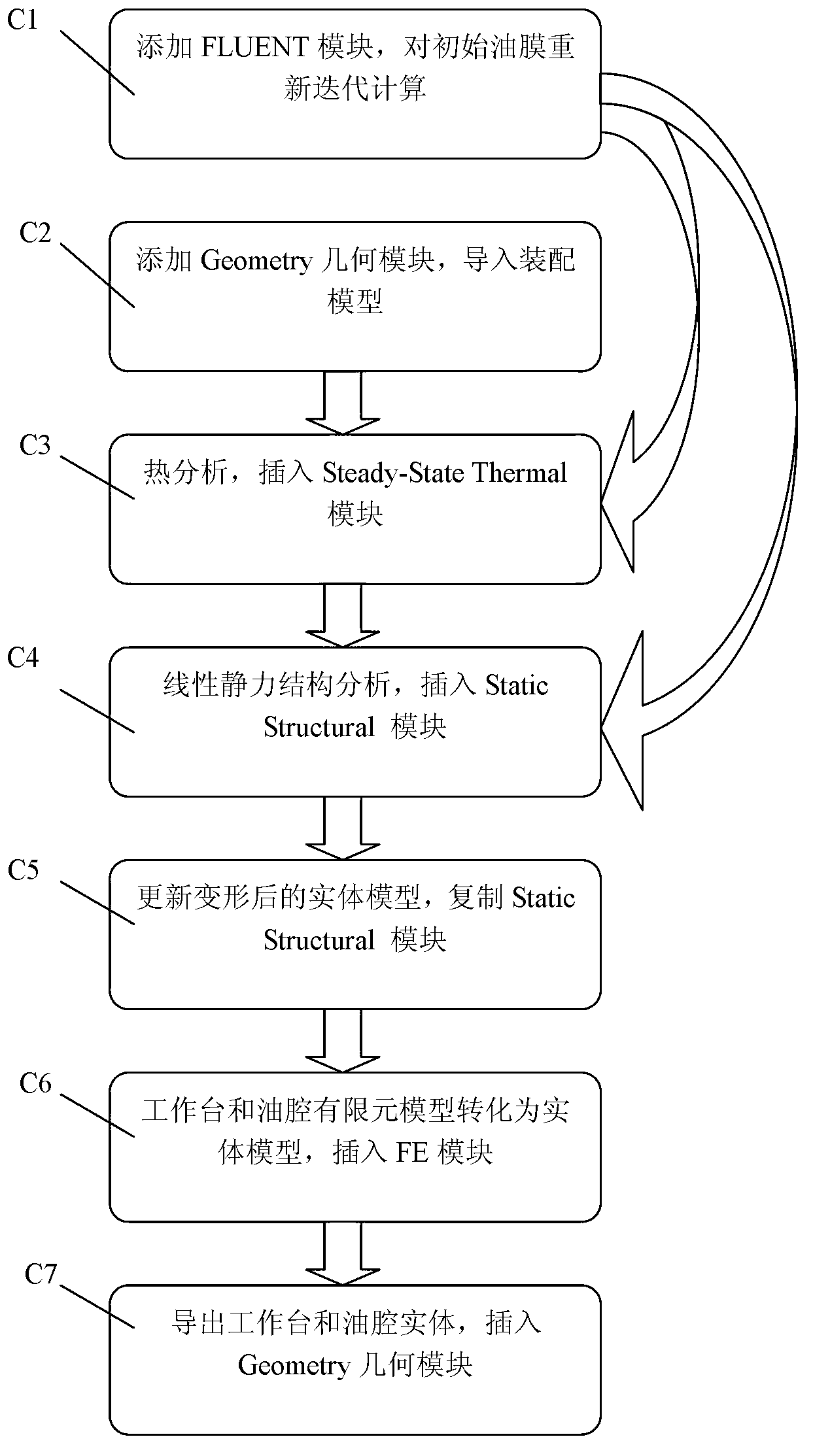
[0025] Specific embodiment three: the difference between this embodiment and specific embodiment one or two is that step C establishes a work flow chart in the ANSYSWOERKBECH software, and performs thermal coupling calculation and analysis on the static pressure thrust bearing as follows:

[0026] Step C1, import the fluid analysis results, add the FLUENT module, import the youmo.cas file in step B into FLUENT and re-calculate iteratively;

[0027] Step C2, import the assembly model, add the Geometry geometric module, and import the zhuangpei.x_t file in step A;

[0028] Step C3, thermal analysis, insert the Steady-State Thermal module, and set the material properties of the workbench, base and oil chamber. Since only thermal analysis and linear structural analysis are required, it is only necessary to fill in the corresponding density, Yang modulus, Poisson's ratio and thermal conductivity; the results of fluid analysis are imported into thermal analysis, and the temperature ...


PUM


Abstract

The invention provides a method for building a lubricating oil film model after thermal mechanical coupling deformation of a hydrostatic thrust bearing to solve the problem that the efficiency and accuracy of workpieces are largely affected by an existing method for building an oil film model. The method includes the steps: A, building a workbench, a base, a sector oil cavity and a model of an initial oil film and assembling the workbench, the base and the oil cavity; B, pre-treating the model of the initial oil film; C, building a flow chart in the workbench and performing thermal mechanical coupling calculation and analysis for the hydrostatic thrust bearing; D, sealing a gap between the workbench and the oil cavity; and E, obtaining a model of a gap lubricating oil film. The method is applied to the field of lubricating oil film models.

Description

technical field [0001] The present invention relates to a method for lubricating oil film models. Background technique [0002] While promoting the application of hydrostatic technology, universities and research institutes at home and abroad have conducted a large number of experiments and theoretical research, including the improvement of the bearing structure of the hydrostatic bearing, the control method of the throttle, and the perfection of the design calculation method. In terms of the performance research of heavy-duty hydrostatic thrust bearings, they all focus on the research of hydrostatic thrust bearings using constant pressure oil supply, and are limited to their experimental devices, selection of throttle types, structural optimization, and different types of throttles. The comparison of cavity structure optimization, bearing characteristics and damping characteristics and other aspects of research. However, there is almost no research on the acquisition of lu...

Claims


Application Information

Patent Timeline
IPC IPC(8): G06F17/50
Inventor 张艳芹范立国于晓东李锐杨晓冬陈瑶
Owner HARBIN UNIV OF SCI & TECH
Why Eureka
Try Eureka