Heat pipe air pre-heater capable of preventing dew point corrosion

An air preheater and dew point corrosion technology, applied in indirect heat exchangers, damage protection, heat exchange equipment, etc., can solve the problems of easy dust accumulation, dew point corrosion and pipe burst, achieve low cost, reduce dew point corrosion, The effect of improving heat exchange efficiency and self-cleaning ability

Inactive Publication Date: 2013-08-07
SOUTH CHINA UNIV OF TECH
View PDF6 Cites 5 Cited by
  • Summary
  • Abstract
  • Description
  • Claims
  • Application Information

AI Technical Summary

Problems solved by technology

[0004] In order to overcome the deficiencies of the existing heat pipe heat exchangers, which are prone to dew point corrosion, pipe bursting, and easy dust accumulation, the present invention provides a heat pipe air that reduces dew point corrosion and pipe bursting, has good heat transfer performance, and has strong self-cleaning ability. Preheater

Method used


Image

  • Heat pipe air pre-heater capable of preventing dew point corrosion
  • Heat pipe air pre-heater capable of preventing dew point corrosion
  • Heat pipe air pre-heater capable of preventing dew point corrosion

Examples


Embodiment 1

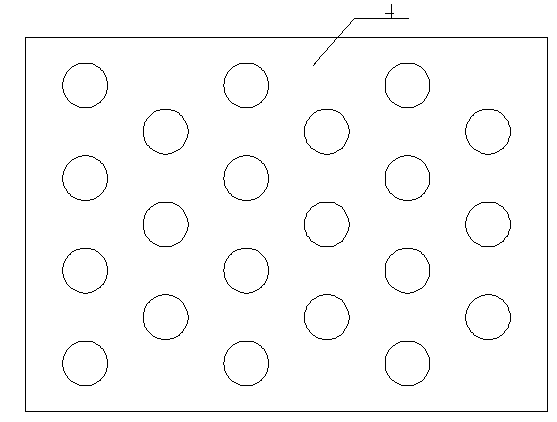
[0020] Such as figure 1 As shown, a heat pipe air preheater for preventing dew point corrosion includes a cuboid box 1, and the box 1 is provided with an upper cold flow chamber 2 and a lower hot flow chamber that separate the inner cavity of the box from each other. The separator 4 of 3 has multiple rows of heat pipes 5 interspersed and welded on the separator 4, and the separator 4 is located in the middle of the heat pipe. The upper sections of all heat pipes 5 are located in the cold flow chamber 2, and the lower sections of the heat pipes 5 are located in the hot flow chamber 3. The outer surfaces of the heat pipes 5 are welded with spiral fins 6 of equal height, and the first two rows of heat pipes near the input port at the left end of the heat flow chamber 3 The total area of ​​the fins 6 of the upper section of 5 is greater than the total area of ​​the fins 6 of the lower section, that is, the pitch of the upper fins 6 is 10mm, and the pitch of the lower fins 6 is 20m...

Embodiment 2

[0026] Compared with Embodiment 1, the difference of this embodiment is that the pitch of the fins 6 on the outer surface of the heat pipe 5 is the same, but the height of the fins 6 is not equal, and the first two rows of heat pipes near the input port at the left end of the heat flow chamber 3 The total area of ​​the fins 6 of the upper section of 5 is greater than that of the lower section, the height of the upper section fins 6 is 30mm, and the height of the lower section fins 6 is 15mm; The area is smaller than the lower section, the height of the lower section fin 6 is 30mm, and the height of the upper section fin 6 is 15mm;


PUM


Abstract

The invention discloses a heat pipe air pre-heater capable of preventing dew point corrosion. The heat pipe air pre-heater comprises a box body, wherein a partition board dividing an inner cavity of the box body into a cold flow cavity and a hot flow cavity is arranged in the box body, and the cold flow cavity and the hot flow cavity are vertically arranged and are not connected with each other. Heat pipes are inserted onto the partition board in penetrating mode, the upper sections of the heat pipes are located in the cold flow cavity, and the lower sections of the heat pipes are located in the hot flow cavity. Spiral fins are connected onto the outer surfaces of all the heat pipes, the total area of the fins on the upper sections of the front two rows of heat pipes located close to an output port at the right end of the hot flow cavity is smaller than that of the fins on the lower sections of the front two rows of heat pipes, the total area of the fins on the upper sections of the last two rows of heat pipes located close to an input port at the left end of the hot flow cavity is larger than that of the fins on the lower sections of the last two rows of heat pipes, and the total areas of the fins on the upper sections and the lower sections of the other heat pipes are identical. The heat pipe air pre-heater can effectively reduce dew point corrosion and high-temperature pipe explosion, is provided with a heat exchange device with high heat exchange efficiency and a self ash removal function, and has the advantages of being efficient, safe and low in cost.

Description

[0001] technical field [0002] The invention relates to the field of heat exchange devices of chemical equipment, in particular to a heat pipe air preheater for preventing dew point corrosion applied to flue gas waste heat recovery technology. Background technique [0003] The heat pipe air preheater is widely used in flue gas waste heat recovery technology due to its high-efficiency heat transfer, safety and reliability. However, the traditional heat pipe heat exchangers used in flue gas waste heat recovery have the following two main disadvantages: 1. Dew point corrosion is easy to occur. When the flue gas temperature decreases and the pipe wall temperature is lower than the dew point, the water vapor in the flue gas will Condensation on the pipe wall, sulfur dioxide, sulfur trioxide and other acid gases in the flue gas dissolve in the water to form an acid solution that corrodes the pipe wall, causing the heat pipe to break and fail. This is the most fatal shortcoming of...

Claims


Application Information

Patent Timeline
Patent Type & Authority Applications(China)
IPC IPC(8): F28D15/02F28F19/00
Inventor 冯名忠潘小坚殷小春王新婷刘露阳梁朝焜林泽生肖凯麟
Owner SOUTH CHINA UNIV OF TECH
Why Eureka
Try Eureka