Eureka AIR delivers breakthrough ideas for toughest innovation challenges, trusted by R&D personnel around the world.

Optical fiber preform cladding fluorine doping method

A fiber preform and cladding technology, which is applied in glass fiber products, manufacturing tools, glass manufacturing equipment, etc., can solve the problem of ensuring the uniformity of fluorine doping in the axial and radial directions, and the difficulty of forming a step-type refractive index profile structure and other problems, to achieve the effect of reducing attenuation, uniform distribution, and reducing OH- content

Active Publication Date: 2013-07-31
ZHEJIANG FUTONG OPTICAL FIBER TECH +1
View PDF8 Cites 41 Cited by
  • Summary
  • Abstract
  • Description
  • Claims
  • Application Information

AI Technical Summary

Problems solved by technology

This method has the following problems: Since the blowtorch sprays fluorine-containing gas to a certain part of the loose body from one direction, it is difficult to ensure the axial and radial uniformity of fluorine doping
The problem caused by this is: since the core layer and cladding layer of the deposited mandrel are both loose bodies containing a large number of pores, when vitrification is doped with fluorine, fluorine not only diffuses into the cladding layer, but also enters the core layer, resulting in It is difficult for fluorine to be selectively doped into the cladding layer to form a refractive index profile structure
Obviously, this method is as difficult to form a step-type refractive index profile structure as the method of the US patent application with the publication number US2002 / 0073740 A1

Method used


Image

  • Optical fiber preform cladding fluorine doping method
  • Optical fiber preform cladding fluorine doping method
  • Optical fiber preform cladding fluorine doping method

Examples


Embodiment 1

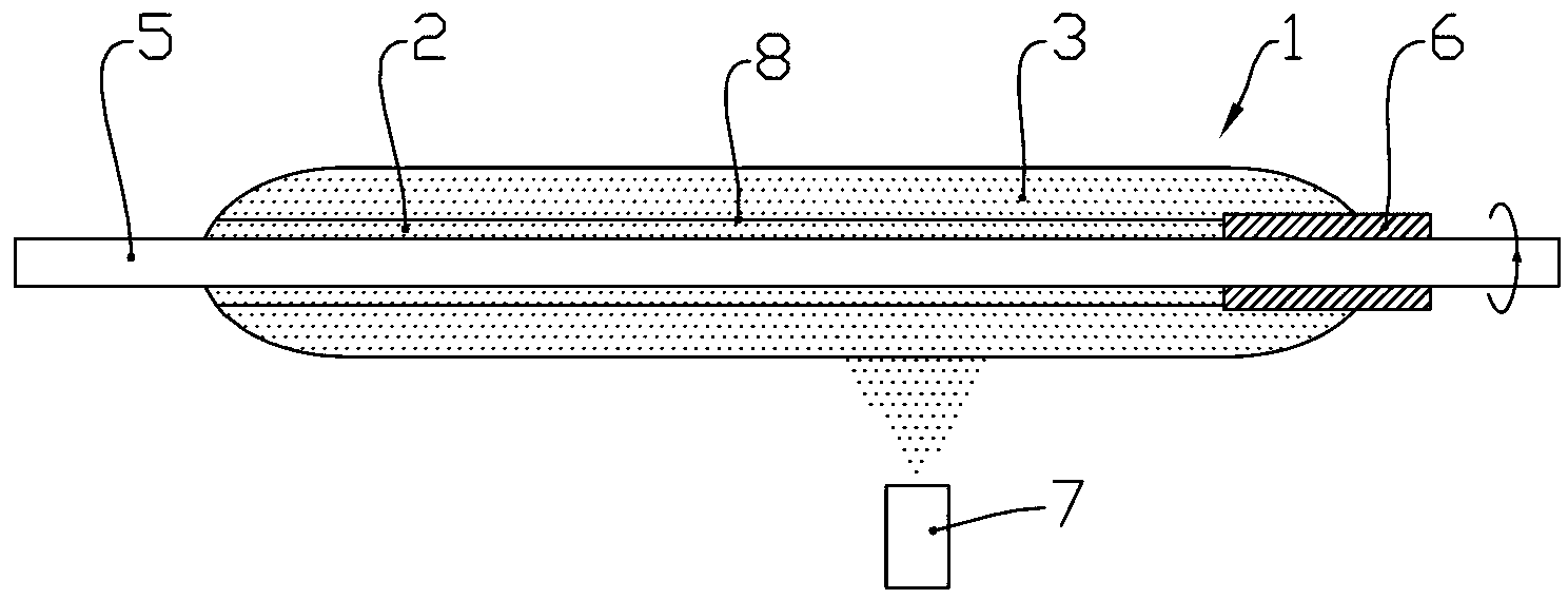
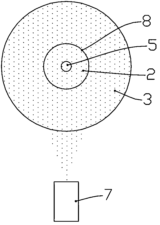
[0076] The mandrel loose body 1 is manufactured by OVD method. Insert the target rod 5 into the tubular handle 6 and install it on the lathe. Gaseous halide raw material SiCl 4 、GeCl 4 The hydrolysis reaction is carried out in an oxygen-hydrogen flame to produce a large amount of SiO 2 doped GeO 2 The particles are deposited onto the target rod 5 . As the target rod 5 moves back and forth, the SiO 2 -GeO 2 The particles are deposited layer by layer on the outer surface of the rotating mandrel loose body 1 . After the core layer loose body 2 is deposited, stop supplying the raw material SiCl in the blowtorch 7 4 and GeCl 4 , heat the outer surface of the loose core layer 2 with an oxyhydrogen flame to vitrify it to form a dense layer 8 . The flow rates of hydrogen and oxygen in the blowtorch 7 are 200 slpm and 90 slpm respectively. Next, feed the raw material SiCl in the blowtorch 7 4 , depositing the inner cladding loose body 3 on the outer surface of the dense laye...

Embodiment 2

[0079] The mandrel loose body 1 is manufactured by the OVD method as described in Example 1. The difference is that when the core layer loose body 2 is deposited, the raw material SiCl 4 The hydrolysis reaction in an oxygen-hydrogen flame produces SiO 2 The particles are deposited onto the target rod 5 to form pure SiO 2 Core loose body 2. After heating to form the dense layer 8 as described in Example 1, the inner cladding loose body 3 is continuously deposited. After the deposition is completed, the ratio of the diameter of the inner cladding loose body 2 to the diameter of the core layer loose body 2 is 5.0. The mandrel loose body 1 has an outer diameter of 100mm and a length of 1800mm.

[0080] Pull out the target rod 5, weld the tubular extension handle 9 to the tubular handle 6, then install the tubular extension handle 9 on the fixture above the vitrification furnace (not shown in the figure), and slowly lower the mandrel loose body 1 Vitrification in a vitrification...

Embodiment 3

[0082] The mandrel loose body 1 is manufactured by the OVD method as described in Example 2. The dense layer 8 at the interface between the loose body of the core layer 2 and the loose body of the inner cladding layer 3 is formed by heating in a heating furnace to obtain pure SiO 2 For the mandrel loose body 1 of the core layer, the ratio of the diameter of the inner cladding loose body 3 to the diameter of the core layer loose body 2 is 5.0. The mandrel loose body 1 has an outer diameter of 100mm and a length of 1200mm.

[0083] Pull out the target rod 5, weld the tubular extension handle 9 to the tubular handle 6, then install the tubular extension handle 9 on the fixture above the vitrification furnace (not shown in the figure), and slowly lower the mandrel loose body 1 Vitrification in a vitrification furnace. The mandrel loose body 1 rotates at a speed of 10 rpm, and gradually descends into the heating zone. First pass inert gas nitrogen purge, then pass through Cl 2 ...


PUM

PropertyMeasurementUnit
densityaaaaaaaaaa
thicknessaaaaaaaaaa
densityaaaaaaaaaa

Abstract

The present invention discloses an optical fiber preform cladding fluorine doping method, which comprises the following steps: depositing a core layer loose body on a target rod; heating the outer surface of the core layer loose body to form a dense layer, such that density of the dense layer is higher than density in the core layer loose body; depositing an inner cladding loose body outside the dense layer to form a core rod loose body comprising the core layer loose body and the inner cladding loose body; taking the target rod out to form a center hole in the center of the core rod loose body; placing the core rod loose body into a glass transition furnace, carrying out heating dewatering in a dewatering atmosphere, and introducing dewatering gas into the center hole during heating; heating the core rod loose body in a fluoride atmosphere, such that fluorine is selectively doped into the inner cladding loose body to form step refraction index distribution; and carrying out glass transition on the core rod loose body, such that the center hole is shrunk, the core layer loose body forms a core layer, and the inner cladding loose body forms an inner cladding so as to form a core rod. With the method, OH<-> content in the core layer can be effectively reduced, attenuation of optical fiber 1383 nm can be reduced, and fluorine distribution in a radial direction of the cladding is uniform.

Description

technical field [0001] The invention relates to a method for manufacturing an optical fiber preform, in particular to a method for doping the cladding of an optical fiber preform with fluorine. Background technique [0002] Optical fiber preform is the raw material for drawing optical fiber. Its basic structure includes a core layer and a cladding layer with a lower refractive index (the cladding layer can also include an inner cladding layer and an outer cladding layer). SiO 2 It is the main glass former used to make optical fiber preforms, and its refractive index can be changed by doping to form a waveguide structure. Generally doped with GeO in the core layer 2 , so that the refractive index of the core layer is higher than that of the cladding pure silica glass. The relative difference between the refractive index of the core layer and the cladding layer is expressed by the relative refractive index difference Δ, and the refractive indices of the core layer and the c...

Claims


Application Information

Patent Timeline
Patent Type & Authority Applications(China)
IPC IPC(8): C03B37/014
CPCC03B2201/12C03B37/01453C03B2203/22
Inventor 冯高峰杨军勇章海峰葛锡良马静
Owner ZHEJIANG FUTONG OPTICAL FIBER TECH
Why Eureka
Eureka Blog
Learn More