


Quick Research
Generate reliable direction feasibility study reports for your R&D in just a few steps.

Technical Q&A
Discover and master advanced knowledge NOW. Basics, ideas, possibilities, all at once.

Find Solutions
As an expert in R&D theories, this can generate solutions to your technical problems instantly.

Evaluate Feasibility
Analyze your overall solution with one click, know your potential R&D risks in advance.

Monitor Landscape
Get weekly tech updates, stay abreast of the latest tech innovations and key insights.
Fiber laser apparatus, and method of detecting abnormality of fiber laser apparatus
A fiber laser, fiber optic technology, applied in laser monitoring devices, lasers, laser parts and other directions, can solve problems such as increased economic losses
- Summary
- Abstract
- Description
- Claims
- Application Information
AI Technical Summary
Problems solved by technology
Method used
Image

Examples
no. 1 approach
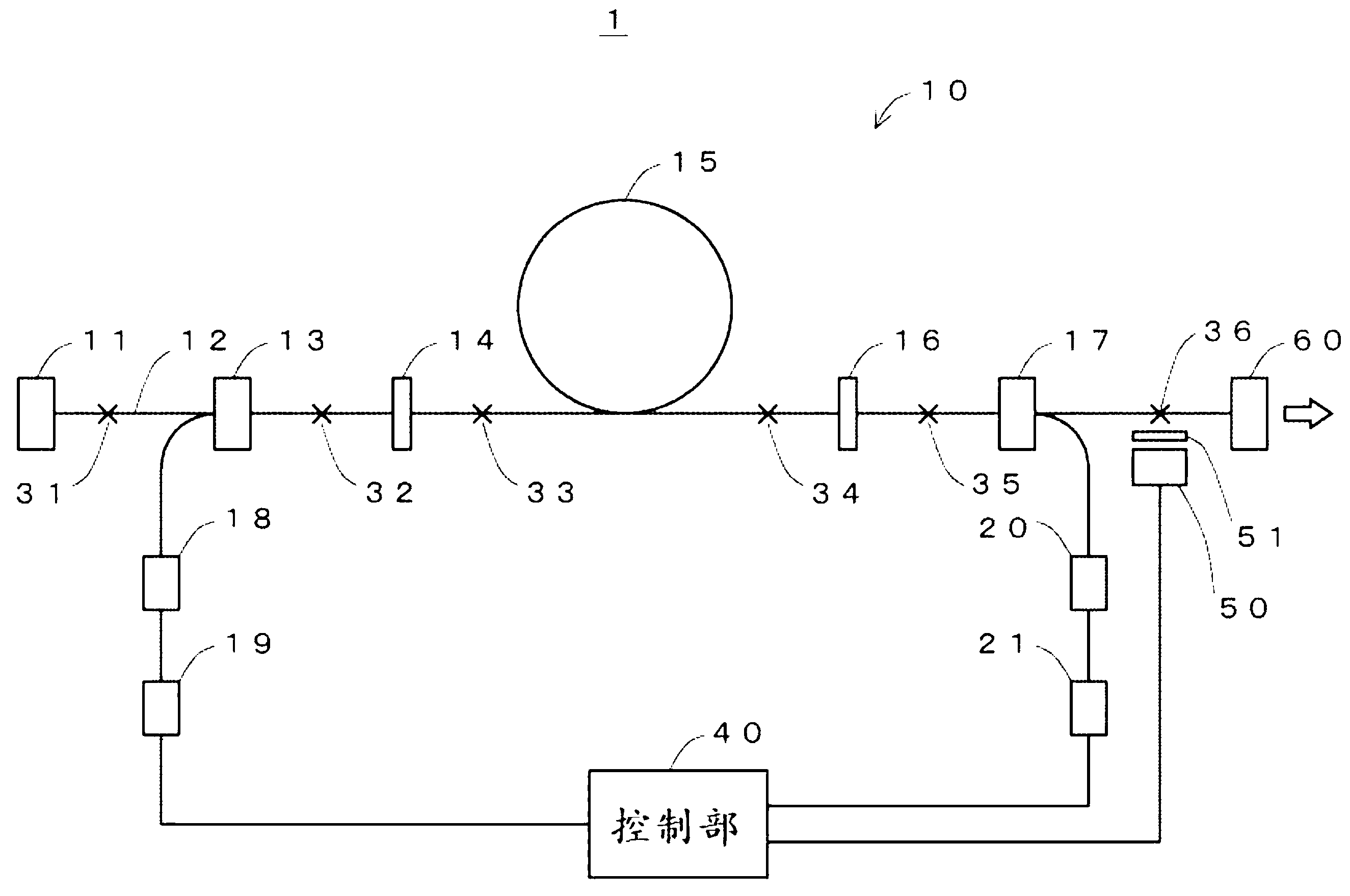
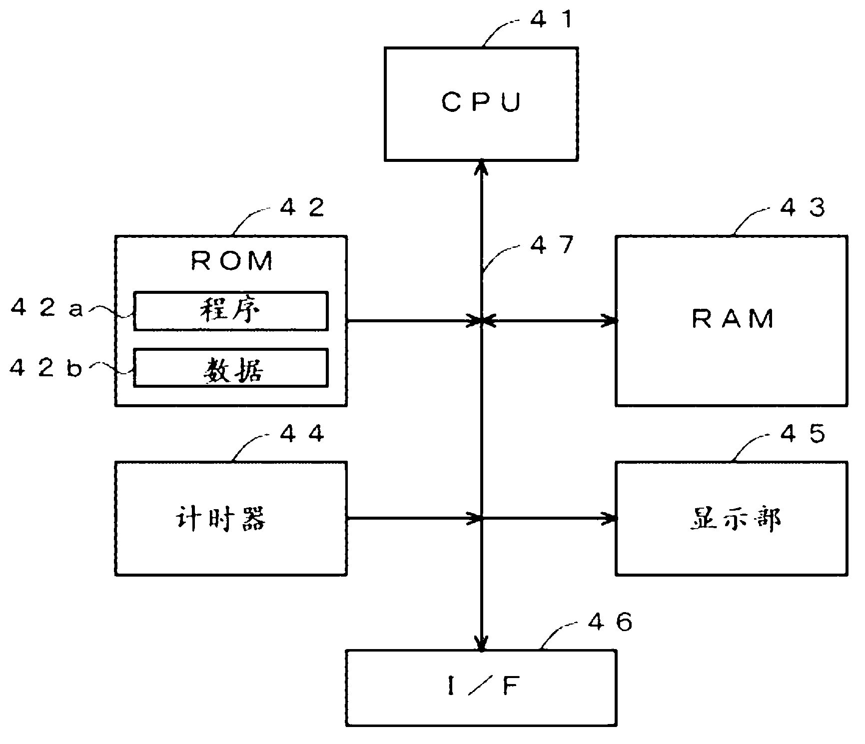
[0059] figure 1 It is a figure which shows the structural example of 1st Embodiment of this invention. As shown in this figure, the fiber laser device 1 of the first embodiment has the following components as main components: a terminal part 11, an optical fiber 12, and an excitation optical multiplexer (TFB (Tapered Fiber Bundle, tapered fiber bundle)) 13, 17 , HR14, amplifying optical fiber 15, OC16, excitation LD (Laser Diode, laser diode) 18, 20, excitation LD driving power 19, 21 (corresponding to the "stop part" in the claim), control part 40 (corresponding to In the "judgment section" in the claims), PD (Photo Diode, photodiode) 50 (corresponding to the "detection section" in the claims), excitation light cut filter 51 (corresponding to the "attenuation section" in the claims ), and the output optics 60. It should be noted that the terminal portion 11, the optical fiber 12, the excitation optical multiplexers 13, 17, HR14, the amplification optical fiber 15, the OC16,...
Embodiment approach
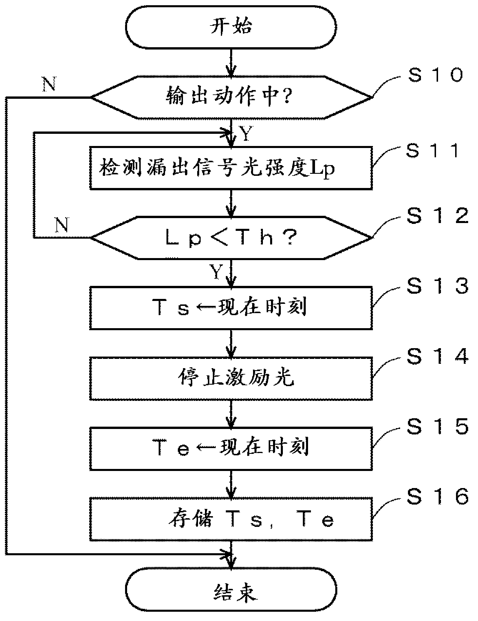
[0080] As described above, according to the first embodiment of the present invention, the leaked signal light from the fusion splicing portion 36 of the optical fiber 12 is detected, and when the intensity Lp of the leaked signal light becomes smaller than the predetermined threshold value Th, it is determined that the optical fiber has occurred. Fuse, so the occurrence of fiber fusing can be reliably detected. In addition, in the first embodiment, since it is possible to detect fiber fusing occurring in any part of the fiber laser device 1 by providing only one PD 50 , it is possible to reliably detect the occurrence of fiber fusing at low cost.
[0081] It should be noted that since the fiber length of each optical component is several tens of centimeters (cm) as described above, in order to prevent the propagation of the fiber fusing to other components, the time from the occurrence of the fiber fusing to the stop of the excitation LD is preferably, for example, within 100...
PUM
 Abstract
Description
Claims
Application Information
 - R&D Engineer
- R&D Manager
- IP Professional
- Industry Leading Data Capabilities
- Powerful AI technology
- Patent DNA Extraction
Browse by: Latest US Patents, China's latest patents, Technical Efficacy Thesaurus, Application Domain, Technology Topic, Popular Technical Reports.
© 2024 PatSnap. All rights reserved.Legal|Privacy policy|Modern Slavery Act Transparency Statement|Sitemap|About US| Contact US: help@patsnap.com