Laser device

A laser device and laser technology, applied in the direction of laser monitoring devices, lasers, semiconductor lasers, etc., can solve the problems of not being able to fully protect optical components, not being able to correctly detect returning light, and being difficult to detect

Pending Publication Date: 2021-07-23
THE FUJIKURA CABLE WORKS LTD
View PDF1 Cites 0 Cited by
  • Summary
  • Abstract
  • Description
  • Claims
  • Application Information

AI Technical Summary

Problems solved by technology

Visible light emitted from the core heated to a high temperature and propagating toward the light source when fiber fusing occurs has a different wavelength band and power from the reflected light reflected from the workpiece, so it is difficult to pass the detection for detecting reflected light. device to correctly detect the
Therefore, in the laser device described in Patent Document 1, the return light cannot be accurately detected, and it is difficult to sufficiently protect the optical components.

Method used


Image

  • Laser device
  • Laser device
  • Laser device

Examples


Embodiment approach

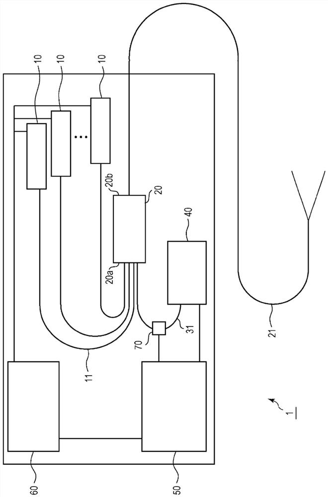
[0061] The configuration of the laser device of this embodiment will be described.

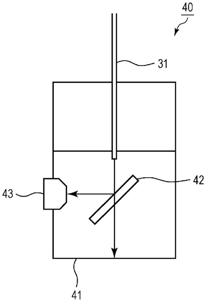
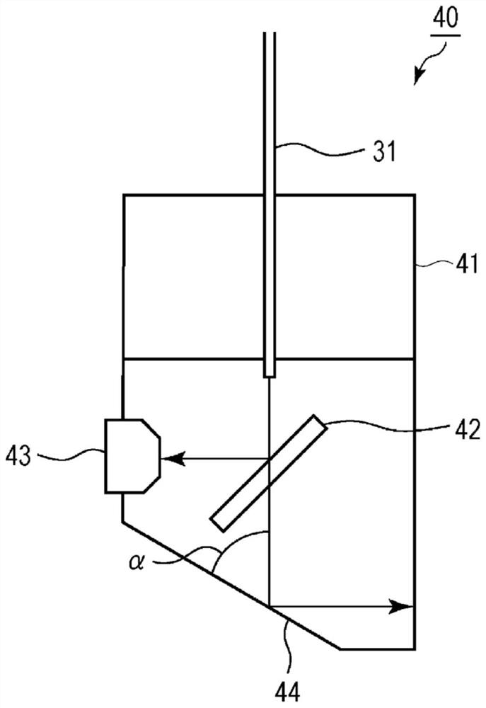
[0062] figure 1 It is a conceptual diagram showing the laser device according to the first embodiment of the present invention. Such as figure 1 As shown, the laser device 1 of this embodiment includes a plurality of light sources 10 , a bridge fiber 20 , a transmission fiber 21 , a monitor fiber 31 , a first photodetector 40 , and a second photodetector 70 as main components. In this embodiment, a multimode fiber is used as the transmission fiber 21 .

[0063] The light source 10 is a laser source that emits signal light of a predetermined wavelength, and is, for example, a fiber laser device or a solid-state laser device. When the light source 10 is a fiber laser device, it is a resonator type fiber laser device or a MO-PA (Master Oscillator Power Amplifier) ​​type fiber laser device. The signal light emitted from each light source 10 is second light having a wavelength included in near-...


PUM

PropertyMeasurementUnit
Diameteraaaaaaaaaa

Abstract

A laser device comprises: at least one light source; a delivery fiber that propagates laser light emitted from the light source; and a first light detection unit and a second light detection unit that are capable of detecting a portion of light propagating in the delivery fiber in a direction opposite to the propagating direction of the laser light. The first light detection unit detects first light included in the wavelength band of visible light, and the second light detection unit detects second light included in the wavelength band of near-infrared light.

Description

technical field [0001] The present invention relates to laser devices. [0002] This application claims priority based on Japanese Patent Application No. 2019-034377 filed in Japan on February 27, 2019, the contents of which are incorporated herein. Background technique [0003] A fiber laser device used as a laser processing machine for cutting or welding metal plates propagates laser light in a transmission fiber and emits it to the outside. In this fiber laser device, reflected light reflected from a workpiece returns toward the fiber laser device, and optical components such as an optical fiber and a laser diode (LD) may be damaged due to accidental heating or the like. Therefore, it is necessary to accurately detect the amount of reflected light and provide feedback to the control of laser output. [0004] In this regard, Patent Document 1 discloses a technique of monitoring both the reflected light propagating through the core and the reflected light propagating thro...

Claims


Application Information

Patent Timeline
IPC IPC(8): H01S3/00H01S3/067
CPCH01S3/005H01S3/0014H01S5/06825B23K26/705B23K26/21B23K26/38H01S3/06708H01S3/094053
Inventor 阪本真一千叶康人清山航山口裕莲沼孝
Owner THE FUJIKURA CABLE WORKS LTD
Why Eureka
Try Eureka