
Hydraulic pipeline leakage online detecting method and device

A technology of hydraulic pipeline and detection method, which is applied in the direction of using liquid/vacuum degree for liquid tightness measurement and measuring the acceleration and deceleration rate of fluid, etc., can solve the problems of waste of resources, environmental pollution, and waste of oil products, etc. The effect of avoiding fire, avoiding the expansion of accidents, reducing environmental pollution and waste of resources

Active Publication Date: 2013-07-24
ANGANG STEEL CO LTD
View PDF8 Cites 9 Cited by
  • Summary
  • Abstract
  • Description
  • Claims
  • Application Information

AI Technical Summary

Problems solved by technology

[0002] At present, the hot rolling production line widely adopts the hydraulic transmission device to transmit power. Compared with the mechanical transmission, the hydraulic cylinder has the advantages of small size and high transmission power. The high temperature of billets and finished products in the rolling production line will cause fires and cause heavy losses; even if the leaked oil does not touch the billets or finished products, it will not cause fires, but will also cause serious environmental pollution and waste of resources
[0003] At present, the method of detecting oil leakage mainly depends on the individual's mastery of the accident plan. Due to the large individual differences, it is difficult to guarantee the effect; or someone just walks to the leakage site and finds it. The liquid level of the oil tank drops to the lower limit and an alarm is issued. This method wastes more oil.

Method used


Image

  • Hydraulic pipeline leakage online detecting method and device

Examples


Embodiment Construction

[0018] The specific embodiment of the present invention will be further described below in conjunction with accompanying drawing:

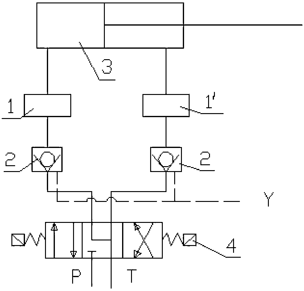
[0019] See figure 1 , is a structural block diagram of an embodiment of an on-line detection device for hydraulic pipeline leakage in the present invention, including a flowmeter 1, the flowmeter 1 is arranged on the oil inlet pipeline of the hydraulic cylinder 3, and the 4-20mA signal output terminal of the flowmeter 1 is connected to the remote computer. The flow meter 1 is closely connected to the outlet port of the one-way valve 2 downstream of the electromagnetic (liquid) reversing valve 4 .

[0020] The present invention measures the oil intake of the hydraulic cylinder and judges the difference between the oil intake and the reference value in real time based on the oil intake when the hydraulic cylinder is qualified, as the basis for the leakage of the hydraulic cylinder and its oil intake pipeline. Taking the two-way hydraulic cylinder ...


PUM


Abstract

The invention relates to the field of hydraulic transmission, in particular to a hydraulic pipeline leakage online detecting method and a device. The hydraulic pipeline leakage online detecting method and the device are characterized in that an oil input amount of a hydraulic cylinder is metered and an oil input amount of a qualified hydraulic cylinder is used as a benchmark and the difference between the oil input amount and a benchmark value is judged in a real-time mode and used as a basis for hydraulic cylinder leakage. The specific steps are as follows: 1) a flow meter is installed on an oil inlet pipeline of the hydraulic cylinder; 2) the hydraulic cylinder is stretched out all the stroke, and cumulative values a0 of the flow meter are measured and used as the benchmark value; 3) during operation of the hydraulic cylinder, a computer detects cumulative flow a at an arbitrary moment when the hydraulic cylinder is full in stoke in a real time mode and when the difference between a and a0 exceeds the upper limit, the fact that the hydraulic cylinder leaks is determined; and 4) a pressure source is cut off. The upper limit is a0*(0.01 - 0.1). Compared with the prior art, the hydraulic pipeline leakage online detecting method and the device have the advantages that an alarming signal can be emitted in time and the pressure source is cut off, environmental pollution and resource waste caused by loss of oil products are reduced and fire disaster is avoided.

Description

technical field [0001] The invention relates to the field of hydraulic transmission, in particular to an online detection method and device for hydraulic pipeline leakage. Background technique [0002] At present, the hot rolling production line widely adopts the hydraulic transmission device to transmit power. Compared with the mechanical transmission, the hydraulic cylinder has the advantages of small size and high transmission power. The high temperature of billets and finished products in the rolling production line will cause fires and cause heavy losses; even if the leaked oil does not touch the billets or finished products, it will not cause fires, but will also cause serious environmental pollution and waste of resources. [0003] At present, the method of detecting oil leakage mainly depends on the individual's mastery of the accident plan. Due to the large individual differences, it is difficult to guarantee the effect; or someone just walks to the leakage site and...

Claims


Application Information

Patent Timeline
Patent Type & Authority Applications(China)
IPC IPC(8): G01M3/28
Inventor 董喜荣董文广
Owner ANGANG STEEL CO LTD
Learn More