
Rain energy collecting and utilizing system for rainwater at roof of high-rise building

A technology for high-rise buildings and rainwater, which is applied to buildings, roof drainage, water supply devices, etc., can solve problems such as lack of corresponding water use measures for water quality classification and utilization, no effective measures for utilizing rain energy resources, and inability to fully exert auxiliary functions. To achieve the effect of reducing external water supply, reducing the pressure of flood control and drainage, and saving land

Inactive Publication Date: 2013-07-24
HOHAI UNIV
View PDF10 Cites 6 Cited by
  • Summary
  • Abstract
  • Description
  • Claims
  • Application Information

AI Technical Summary

Problems solved by technology

[0004] To sum up, the existing invention can preliminarily realize rainwater harvesting and storage, but there are the following problems: 1) no effective measures for utilizing rain energy resources; 2) lack of corresponding water use measures considering water quality graded utilization; 3) separate construction is required The rainwater transmission pipe network and storage tanks covering an area; 4) The auxiliary function of collecting a part of the flood for the city, which can distribute and store rainwater in the case of heavy rain, cannot be fully utilized; 5) Need to occupy additional valuable land in the city

Method used


Image

  • Rain energy collecting and utilizing system for rainwater at roof of high-rise building

Examples


Embodiment Construction

[0015] Below in conjunction with accompanying drawing, the present invention is described in further detail:

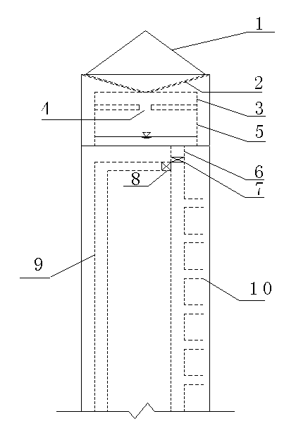
[0016] Such as figure 1 As shown, its structure of the present invention comprises the water collection slope 1 of building roof, and the bottom of water collection slope 1 is connected with simple physical and chemical purification device 3 through rainwater pipe 2, and simple physical and chemical purification device 3 communicates with connecting hole 4 water storage tank 5, and water storage tank 5 A water pipe 6 is connected to the bottom of each user unit, and the flushing water pipes 10 of each user unit are connected to the water pipe 6 . The top of water pipe 6 is also connected with traditional water supply pipe 9. The simple physical and chemical purification device 3 and the water storage tank 5 are arranged in the attic on the top floor of the building.

[0017] The upper end of the water pipe 6 and the interface between the traditional water supply pip...


PUM


Abstract

The invention discloses a rain energy collecting and utilizing system for rainwater at a roof of a high-rise building. The rain energy collecting and utilizing system is characterized by structurally comprising a water collecting slope of a building roof, wherein the bottom of the water collecting slope (1) is connected with a simple physical and chemical purification device (3) through a rainwater pipe (2), the simple physical and chemical purification device (3) is communicated with a water storage tank (5) through a connecting hole (4), the bottom of the water storage tank (5) is connected with a water consumption pipe (6), a toilet flushing water consumption pipe (10) of each user unit is respectively connected to the water consumption pipe (6), and the upper part of the water consumption pipe (6) is also connected with a traditional water supply pipe (9). The rain energy collecting and utilizing system has the advantages that the rainwater is accumulated, meanwhile, the rain energy of the rainwater at the top of the high-rise building is accumulated, the energy source is fully utilized, in addition, the classification utilization of water quality is realized, the rainwater is used for flushing toilets, a purification system is simplified, in addition, matched pipe networks and facilities for rainwater collection are reduced in a mode of both production and use by self, meanwhile, the contribution to rain blockage and accumulation for urban flood control from the source is made, and high popularization values are realized.

Description

technical field [0001] The invention relates to high-efficiency utilization of water resources, especially rainwater resource utilization technology, and specifically refers to a high-rise building rainwater and rain energy collection and utilization and distributed flood control and storage system. Background technique [0002] China is a country seriously short of water resources. The per capita water resources are only 1 / 4 of the world's per capita, and the water resources are unevenly distributed in time and space. Water-scarce areas cannot just wait for cross-basin water transfers, and should fully expand and recycle local water resources. Among them, urban rainwater is a water resource that has not been fully utilized at present. Incomplete utilization of rainwater resources is not only a waste of water resources, but also a waste of water. Energy resources are wasted, and the problem of urban flood control caused by heavy rain cannot be ignored. At present, my countr...

Claims


Application Information

Patent Timeline
Patent Type & Authority Applications(China)
IPC IPC(8): E03B3/02E04D13/04
CPCY02A20/108
Inventor 魏宇航吴都唐德善卜立峰卞彬
Owner HOHAI UNIV
Learn More