Field emission cathode structure and manufacturing method based on sea urchin type nickel particle template

A field emission cathode and nickel particle technology, which is applied in cold cathode manufacturing, electrode system manufacturing, discharge tube/lamp manufacturing, etc., can solve the problem of emission uniformity, poor stability, difficulty in controlling the distribution density of emission tips, and difficulty in effectively achieving vertical emission. Orientation, uniform dispersion of carbon nanostructures and other issues, to achieve the effect of stable electron emission and small open electric field

Active Publication Date: 2015-10-14
FUZHOU UNIV
View PDF2 Cites 0 Cited by
  • Summary
  • Abstract
  • Description
  • Claims
  • Application Information

AI Technical Summary

Problems solved by technology

However, due to the limitations of the current preparation and processing technology, it is difficult to effectively achieve vertically oriented and uniformly dispersed carbon nanostructures, whether it is in-situ growth or post-layout technology.
Therefore, most of the tips cannot point to the anode, and the distribution density of the emission tips is not easy to control, resulting in poor emission uniformity and stability

Method used


Image

  • Field emission cathode structure and manufacturing method based on sea urchin type nickel particle template
  • Field emission cathode structure and manufacturing method based on sea urchin type nickel particle template

Examples


Embodiment 1

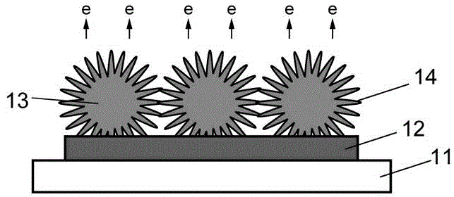
[0034] A field emission cathode structure based on a sea urchin-type nickel particle template provided in the first embodiment of the present invention includes: a substrate 11; a bottom electrode layer 12 disposed on the substrate; and sea urchin-type nickel particles 13 disposed on the The metal bottom electrode layer is used as a template; the surface of the template is covered with nanometer material 24 . In one embodiment of the present invention, the sea urchin-type nickel particles have a two-layer structure of inner and outer layers, and the outer layer is a nickel nanocone 14 to regulate the orientation and distribution of field emission points. The nickel nanocones are radially distributed in the The surface of the template, and part of the nickel nanocones point to the anode. The nickel particle size is 0.3-15 μm, and the cone-point spacing of the nickel nanocone is 0.05-2 μm. The nanomaterial can be a nickel oxide film prepared by in-situ thermal oxidation, or a t...

Embodiment 2

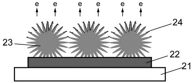
[0043] A method for preparing a field emission cathode structure based on a sea urchin-type nickel particle template provided in the second embodiment of the present invention includes the following steps:

[0044] (1) Prepare the bottom electrode layer 22 on the substrate 21 made of polyvinyl chloride PVC, the process is the same as step 1) of the first embodiment.

[0045] (2) The nickel particle template 23 is prepared on the bottom electrode layer 22 , the process is the same as step 2) of the first embodiment.

[0046] (3) The electron emission material 24 is prepared on the template 23 .

[0047]The material used for the electron emission material 24 can be zinc oxide, tin oxide, magnesium oxide, copper oxide, titanium oxide, manganese oxide, iron oxide, cobalt oxide, nickel oxide, silver oxide, tungsten oxide, lead oxide, bismuth oxide, aluminum nitride A nanomaterial or a composite material composed of multiple nanomaterials, or a nanomaterial or multiple nanomaterial...


PUM

PropertyMeasurementUnit
sizeaaaaaaaaaa

Abstract

The invention relates to a field emission cathode structure based on a sea urchin type nickel particle template and a manufacturing method. The field emission cathode structure based on the sea urchin type nickel particle template comprises a metal base electrode layer, the sea urchin type nickel particle template arranged on the base electrode layer and nanometer materials or film, wherein the nanometer materials or the film is coated on the surface of nickel particles. According to the field emission cathode structure based on the sea urchin type nickel particle template, the orientation and the density of distribution of the tip end of a field emission cathode are regulated and controlled by means of the template, field emission performance is improved by means of the nanometer materials coated on the template, and the difficult problem that the performance of field emission parts can not be controlled is solved. The field emission cathode structure based on the sea urchin type nickel particle template is low in working voltage, high in electronic emission efficiency, stable and reliable in emission, and simple in preparation technology.

Description

technical field [0001] The invention belongs to the technical field of vacuum electronics and relates to the field of flat panel display, in particular to a field emission cathode structure and a manufacturing method based on a sea urchin type nickel particle template. Background technique [0002] Field Emission Display (Field Emission Display, FED) is a new type of device that emits electrons from the cathode of the back substrate to bombard the fluorescent layer of the front substrate to emit light. It is the product of the combination of flat panel display and vacuum microelectronics. FED is considered to be the flat panel display that is most likely to compete with plasma display (PDP) and liquid crystal display (LCD). It combines the advantages of both cathode ray tube display (CRT) and LCD, with fast response speed, wide viewing angle, With advantages such as high brightness, high resolution, good color reproducibility, high and low temperature resistance, vibrati...

Claims


Application Information

Patent Timeline
Patent Type & Authority Patents(China)
IPC IPC(8): H01J29/04H01J9/02
Inventor 胡海龙郭太良张典李福山杨尊先周雄图张永爱叶芸
Owner FUZHOU UNIV
Why Eureka
Try Eureka