
Method and device utilizing low-grade waste heat

A low-grade, waste heat technology, used in machines that use waste heat, machine operation, energy-saving heating/cooling, etc. It can solve the problems of poor heat exchanger economy, waste of cooling capacity, and large heat exchange area, and achieve effective utilization. , The requirements for material and process control are reduced, and the economy is good.

Inactive Publication Date: 2013-07-03
ENN SCI & TECH DEV
View PDF5 Cites 0 Cited by
  • Summary
  • Abstract
  • Description
  • Claims
  • Application Information

AI Technical Summary

Problems solved by technology

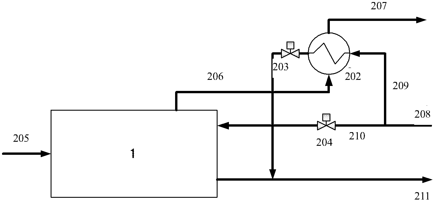
If the temperature of the heating water main road 208 is low, the requirements for the flue gas heat exchanger 202 are high, and it must be able to handle both sensible heat transfer and latent heat transfer, which is not economical
[0004] There are two major technical defects in the existing technical solutions. One is that the waste heat recovery of the flue gas of the direct combustion engine has not been utilized in cascades. The physical properties of the flue gas are very different in the gaseous section and the condensation section. The smoke temperature is above 160°C, and the condensation temperature is around 80°C. If there is no distinction between two types of heat exchangers, the economy of the heat exchanger will become poor and the heat exchange area will be larger; the second is the direct combustion engine The heat of the flue gas does not match its rated thermal power. When using refrigeration to absorb waste heat, even if the latent heat of the flue gas is included, it can only meet about 25% of its rated power, and the rest of the cooling capacity is wasted because no corresponding waste heat source can be found

Method used


Image

  • Method and device utilizing low-grade waste heat
  • Method and device utilizing low-grade waste heat

Examples


Embodiment Construction

[0053] Specific embodiments of the present invention will be described below with reference to the accompanying drawings.

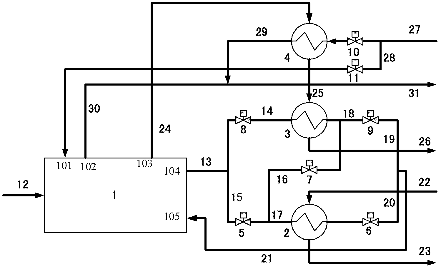
[0054] see figure 2 Describe the method for utilizing low-grade waste heat of the present invention, which includes: introducing the flue gas discharged from the absorption direct combustion engine 1 into the flue gas heat exchanger 4 and recovering the sensible heat of the flue gas; The flue gas is introduced into the flue gas condensing heat exchanger 3 and the latent heat recovery is performed on the flue gas after recovering the sensible heat; the flue gas after the latent heat is recovered is discharged, wherein the absorption direct combustion engine 1 is In the heating season, it operates in the cooling season mode, the recovered sensible heat is replaced by the hot water discharged from the circulating heating water outlet of the absorption direct combustion engine 1, and the recovered latent heat is replaced by the absorption direct combustion e...


PUM


Abstract

The invention provides a method utilizing low-grade waste heat. The method comprises the following steps: smoke emitted by an absorption type direct-fired machine is introduced into a gas-gas heater to be subjected to sensible heat recovery; the smoke subjected to the sensible heat recovery is introduced into a smoke condensation type heat exchanger to be subjected to the latent heat recovery; the smoke subjected to latent heat recovery is emitted, the absorption type direct-fired machine is in operation in a cooling season mode in heating; and sensible heat recovered is transferred to hot water discharged from a circulating heating water outlet of the absorption type direct-fired machine, and the latent heat recovered is transferred to cool water discharged from the circulating heating water outlet of the absorption type direct-fired machine. The invention further provides a device utilizing low-grade waste heat, which comprises the absorption type direct-fired machine, a heating water input branch circuit, a heating water output branch circuit, a smoke heat exchanger and the smoke condensation type heat exchanger; the heating water input branch circuit is connected with a circulating heating water inlet, and the heating water output branch circuit is connected with the circulating heating water outlet; the smoke heat exchanger is used for sensible heat recovery to the smoke emitted from a smoke outlet of the absorption type direct-fired machine; and the smoke condensation type heat exchanger is used for latent heat recovery to the smoke subjected to sensible heat recovery. The method can improve the heat utilization rate of the direct-fired machine.

Description

technical field [0001] The invention relates to a method for utilizing low-grade waste heat and a device for utilizing low-grade waste heat. Background technique [0002] In the prior art, the waste heat recovery scheme of absorption direct-fired engine is mainly divided into two categories, one is to recover flue gas sensible heat by installing a flue gas heat exchanger on the flue of the direct-fired engine, and the other is to recover the sensible heat of the flue gas through the flue A condensing heat exchanger is installed to recover the sensible heat and part of the latent heat of the flue gas. The waste heat recovery of circulating cooling water is generally realized by electric drive heat pump. [0003] figure 1 It is the process flow of waste heat recovery of conventional absorption direct combustion engine. At present, the conventional absorption direct-fired engine system turns on the heating mode during the heating season, and its form is very similar to a gas...

Claims


Application Information

Patent Timeline
Patent Type & Authority Applications(China)
IPC IPC(8): F25B15/06F25B27/02F25B41/04F25B41/20
CPCY02B30/625Y02A30/274
Inventor 仵浩刘长青
Owner ENN SCI & TECH DEV
Learn More