Jet yarn spinning machine for electrostatic-spun nanofibers and use method thereof
A technology of air-jet spinning machine and nanofiber, which is applied in the direction of spinning machine, open-end spinning machine, continuous winding spinning machine, etc.
- Summary
- Abstract
- Description
- Claims
- Application Information
AI Technical Summary
Problems solved by technology
Method used
Image
Examples
Embodiment 1
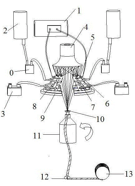
[0033] Example 1: Refer to attached figure 1 , 2 , 3, 4, an electrospinning nanofiber air-jet spinning machine, including a metering pump 0, a high-voltage electrostatic generator 1, a liquid storage tank 2, a cross-flow air pump 3, an accumulation unit 4, a spinning unit 8, and a semicircular base 9. Concentrator 10, nozzle twister 11, yarn delivery roller 12 and winding mechanism 13.
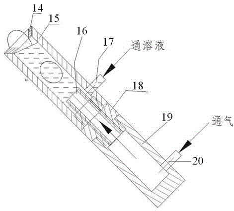
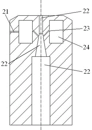
[0034] The spinning unit 8 is formed by connecting the spinneret 15 with the air chamber 19 through the intermediate connecting body 18. The intermediate connecting body 18 is equipped with a vertically upward air jet tube 16; there is a liquid inlet 17 below the spinning tube 15, and the liquid inlet Mouth 17 is lower than the upper end of jet pipe 16, and air inlet 20 is arranged below air chamber 19; Protective ring 14 is equipped with on the top of spinneret 15, prevents solution from overflowing when spinning; The inner diameter of spinneret 15 is 10 mm, the height of the spinneret 1...
Embodiment 2
[0038] Example 2: A method utilizing the air-jet spinning machine of embodiment 1 to continuously prepare electrospun nanofiber yarns, comprising the following steps:
[0039] (1) Dissolve polyacrylonitrile (abbreviation: PAN, weight-average molecular weight: 80,000) in N,N-dimethylformamide (DMF) to prepare a spinning solution with a mass concentration of 13%, and fill it into the stock solution jar 2. The metering pump 0 sends the PAN solution in the liquid storage tank 2 evenly into the spinneret 15 of each spinning unit 8 through the infusion tube 6. The liquid level of the PAN solution is lower than the upper surface of the spinneret 15 and higher than The upper end surface of the trachea 16.
[0040] (2) The cross-flow air pump 3 sends the air flow evenly through the air delivery pipe 7 into the air chamber 19 of each spinning unit 8, and the air flow is sprayed upward through the air injection pipe 16, so that the PAN solution forms a hollow space on the upper end su...
Embodiment 3
[0047] Example 3 : Refer to attached figure 1 , 2 , 3 and 4, an electrospinning nanofiber air-jet spinning machine, including a metering pump 0, a high-voltage electrostatic generator 1, a liquid storage tank 2, a cross-flow air pump 3, a gathering unit 4, a spinning unit 8, and a semicircular base 9. Concentrator 10, nozzle twister 11, yarn delivery roller 12 and winding mechanism 13.
[0048] The spinning unit 8 is formed by connecting the spinneret 15 with the air chamber 19 through the intermediate connecting body 18. The intermediate connecting body 18 is equipped with a vertically upward air jet tube 16; there is a liquid inlet 17 below the spinning tube 15, and the liquid inlet The mouth 17 is lower than the upper end of the jet pipe 16, and the air inlet 20 is arranged below the air chamber 19; the top of the spinneret 15 is equipped with a protective ring 14 to prevent the solution from overflowing during spinning; the inner diameter of the spinneret 15 is 20 mm,...
PUM
| Property | Measurement | Unit |
|---|---|---|
| height | aaaaa | aaaaa |
| height | aaaaa | aaaaa |
| diameter | aaaaa | aaaaa |
Abstract
Description
Claims
Application Information
 - Generate Ideas
- Intellectual Property
- Life Sciences
- Materials
- Tech Scout
- Unparalleled Data Quality
- Higher Quality Content
- 60% Fewer Hallucinations
Browse by: Latest US Patents, China's latest patents, Technical Efficacy Thesaurus, Application Domain, Technology Topic, Popular Technical Reports.
© 2025 PatSnap. All rights reserved.Legal|Privacy policy|Modern Slavery Act Transparency Statement|Sitemap|About US| Contact US: help@patsnap.com


