Molybdenum foil mesh for transmission microscope and scanning microscope and method of making the same
A scanning microscope and transmission microscope technology, applied in the field of molybdenum foil mesh, can solve the problems of no disclosure, and achieve the effect of not easy to be polluted, not easy to be corroded, and high hardness
- Summary
- Abstract
- Description
- Claims
- Application Information
AI Technical Summary
Problems solved by technology
Method used
Image
Examples
Embodiment 1
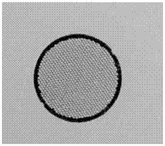
[0019] A molybdenum foil with a thickness of 0.01mm was selected and produced according to the following steps to obtain figure 1 The outer diameter shown is 3mm, the mesh number is 600 mesh, and the mesh is a molybdenum foil mesh with square holes.
[0020] The first step (1) is drawing: first draw manually according to the requirements of the required molybdenum foil mesh, then transfer the manual drawing sketch to the computer for accurate drawing, and then print out the black and white negatives at a ratio of 1:1, forming a pattern on the negatives A picture opposite to the real molybdenum mesh, also called a positive and negative film, as a target for making the real thing.
[0021] Step (2) is molybdenum foil treatment: the surface of the molybdenum foil is cleaned and dried with an ordinary kitchen fume net; the ordinary kitchen fume net is purchased from Beijing Lvsan Chemical Co., Ltd., and its model is Q / HDLSH008.
[0022] The (3) step is glue coating: use conventio...
Embodiment 2
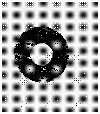
[0032] A molybdenum foil with a thickness of 0.05mm was selected and produced according to the following steps to obtain figure 2 The outer diameter shown is 3.05mm, the number of mesh holes is 1 mesh, and the mesh is a molybdenum foil mesh with round holes.
[0033] The first step (1) is drawing: first draw manually according to the requirements of the required molybdenum mesh, then transfer the manual drawing sketch to the computer for accurate drawing, and then print out the black and white negative film at a ratio of 1:1; form a sheet on the negative film The picture opposite to the real molybdenum mesh is also called positive and negative film.
[0034]Step (2) is molybdenum foil treatment: the surface of the molybdenum foil is cleaned and dried with an ordinary kitchen fume net; the ordinary kitchen fume net is purchased from Beijing Lvsan Chemical Co., Ltd., and its model is Q / HDLSH008.
[0035] The (3) step is gluing: use ultraviolet negative photoresist and negative...
Embodiment 3
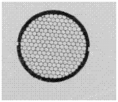
[0045] A molybdenum foil with a thickness of 0.02mm was selected and produced according to the following steps to obtain image 3 The outer diameter shown is 3.02mm, the number of mesh holes is 200 mesh, and the mesh is molybdenum foil mesh with honeycomb holes.
[0046] The first step (1) is drawing: first draw manually according to the requirements of the required molybdenum mesh, then transfer the manual drawing sketch to the computer for accurate drawing, and then print out the black and white negative film at a ratio of 1:1; form a sheet on the negative film The picture opposite to the real molybdenum mesh is also called positive and negative film.
[0047] Step (2) is molybdenum foil treatment: the surface of the molybdenum foil is cleaned and dried with an ordinary kitchen fume net; the ordinary kitchen fume net is purchased from Beijing Lvsan Chemical Co., Ltd., and its model is Q / HDLSH008.
[0048] The (3) step is gluing: use ultraviolet negative photoresist and nega...
PUM
| Property | Measurement | Unit |
|---|---|---|
| thickness | aaaaa | aaaaa |
| thickness | aaaaa | aaaaa |
| thickness | aaaaa | aaaaa |
Abstract
Description
Claims
Application Information
 - R&D
- Intellectual Property
- Life Sciences
- Materials
- Tech Scout
- Unparalleled Data Quality
- Higher Quality Content
- 60% Fewer Hallucinations
Browse by: Latest US Patents, China's latest patents, Technical Efficacy Thesaurus, Application Domain, Technology Topic, Popular Technical Reports.
© 2025 PatSnap. All rights reserved.Legal|Privacy policy|Modern Slavery Act Transparency Statement|Sitemap|About US| Contact US: help@patsnap.com


