Eureka AIR delivers breakthrough ideas for toughest innovation challenges, trusted by R&D personnel around the world.

Diamond optical fiber and manufacturing method thereof

A manufacturing method and diamond technology, applied in cladding optical fiber, optical waveguide light guide, metal material coating technology, etc., can solve the problems of high output power, etc., and achieve simple structure, wide transmittable wavelength and high transmittance Effect

Inactive Publication Date: 2013-06-05
XIAN JINHE OPTICAL TECH
View PDF0 Cites 1 Cited by
  • Summary
  • Abstract
  • Description
  • Claims
  • Application Information

AI Technical Summary

Problems solved by technology

The wavelength of the carbon dioxide laser is 10.6 microns. Due to its high output power, it has good application prospects in the fields of industry and medical treatment. However, the existing crystal fiber or hollow fiber cannot transmit a 10.6 micron laser larger than 50 watts for a long time.
However, due to the limitation of the wavelength range of the existing optical fiber transmission, the monitoring range of the fiber optic spectrometer can only range from ultraviolet to near infrared, and the performance of optical fiber is one of its limiting factors

Method used

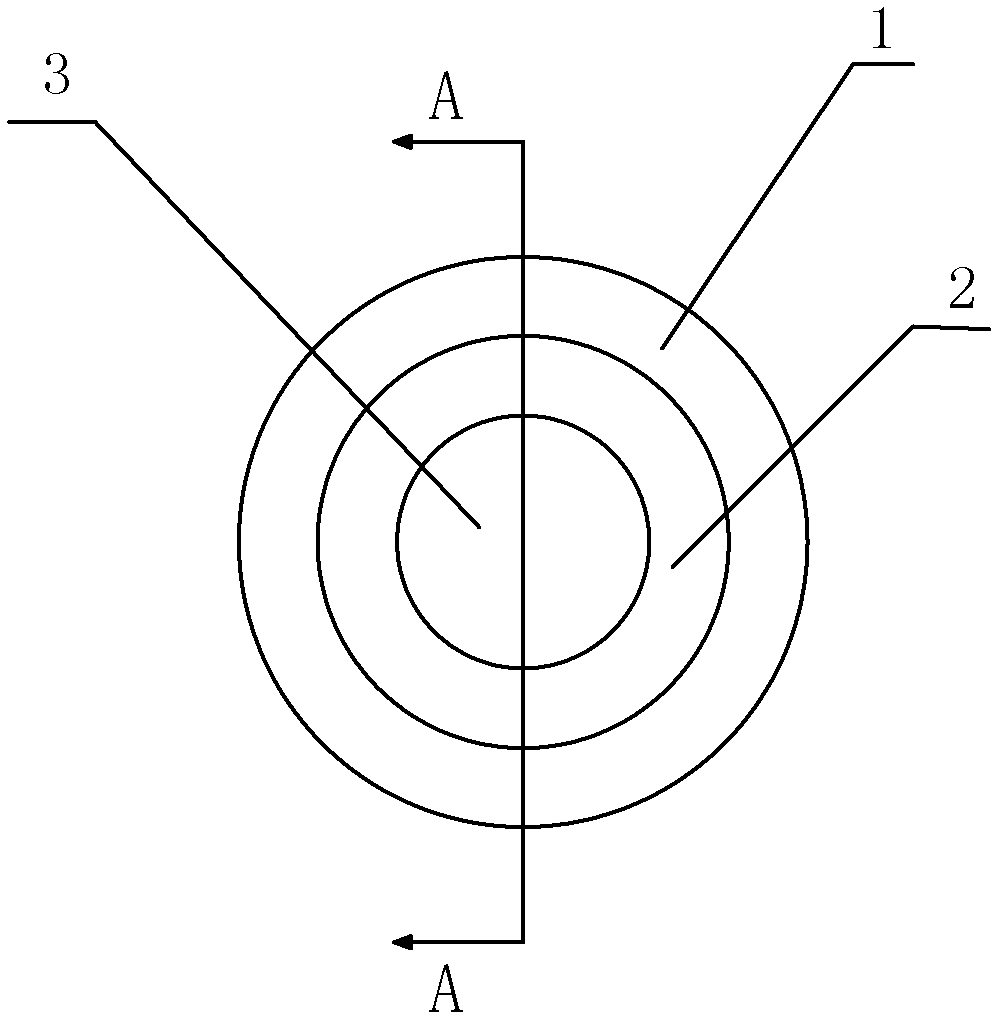
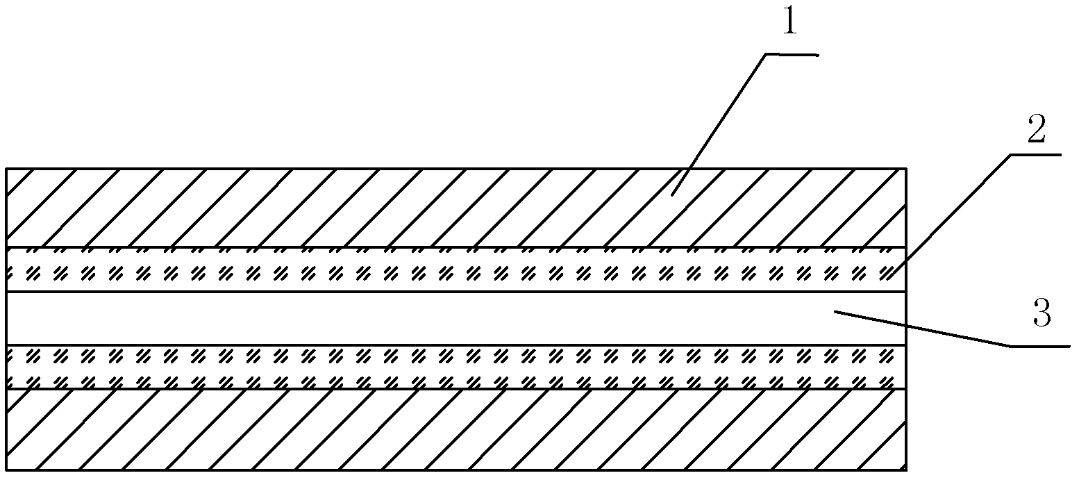

Image

  • Diamond optical fiber and manufacturing method thereof
  • Diamond optical fiber and manufacturing method thereof
  • Diamond optical fiber and manufacturing method thereof

Examples


Embodiment 1

[0028] Such as figure 1 and figure 2 As shown, a diamond optical fiber includes a hollow conduit 1, the inner wall of the hollow conduit 1 is coated with a diamond film 2, and the thickness of the diamond film 2 is between 1 nanometer and 10 millimeters. The diamond film can be a diamond-like film; the optical signal can be transmitted through the diamond film 2 and the through hole 3 of the hollow conduit 1, and has the characteristics of wide wavelength and high transmittance.

[0029] Such as figure 1 and figure 2 As shown, the through hole in the center of the hollow conduit 1 is the through hole 3 .

[0030] In this embodiment, the hollow conduit 1 is a non-metallic hollow conduit, such as silicon material, metal material, metal alloy material, polymer material, ceramic material or glass material; the non-metallic material may be single crystal silicon or the like.

[0031] Preferably, the hollow conduit 1 whose inner wall is coated with the diamond film 2 is a soli...

Embodiment 2

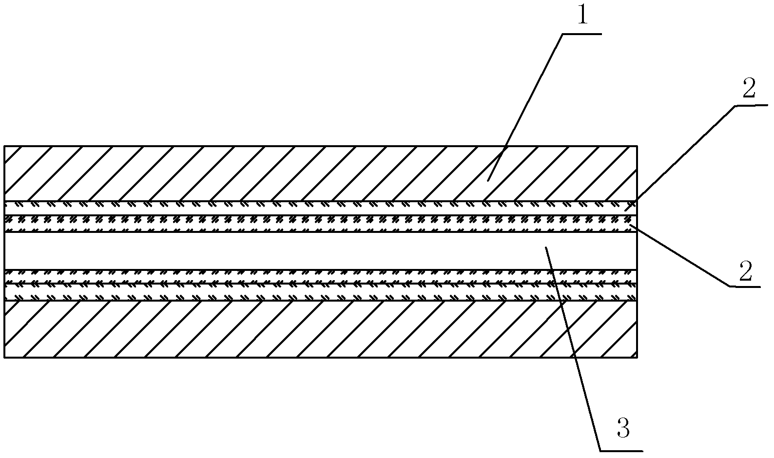
[0042] Such as image 3 As shown, the difference between this embodiment and Embodiment 1 is that the number of the diamond film 2 is two layers.

[0043] In this embodiment, the structures, connections and working principles of other parts are the same as those in Embodiment 1.


PUM

PropertyMeasurementUnit
thicknessaaaaaaaaaa
thicknessaaaaaaaaaa

Abstract

The invention discloses diamond optical fiber and a manufacturing method thereof. The optical fiber is the diamond optical fiber which comprises a hollow conduit, wherein a diamond film is plated on the inner wall of the hollow conduit, and the thickness of the diamond film is ranged from 1 nanometer to 10 millimeters. The manufacturing method of the diamond optical fiber comprises the following steps: (1) washing the inner surface of the hollow conduit with pure water and drying the inner surface of the hollow conduit after the inner surface of the hollow conduit is corroded by acid, (2) leading methane and hydrogen into the hollow conduit, disposing the hollow conduit with radio frequency or microwave to enable plasma to form in the cavity of the hollow conduit, and thus the diamond film is precipitated on the inner wall of the hollow conduct, (3) placing the hollow conduit with the diamond film being precipitated on the inner wall of the hollow conduit in a sealed container, heating continuously more than 5 minutes under the condition that temperature is less than 800 DEG C, and taking out an end product. The diamond optical fiber is made of hollow conduit with the diamond film plated on the inner wall of the hollow conduit layer, the transmission wavelength of the diamond optical fiber can be transmitted from an ultraviolet wave band to a far infrared wave band, and a high-power lasher can be transmitted, and the diamond conduit has certain bendability and high promotion value.

Description

technical field [0001] The invention relates to an optical fiber and a manufacturing method, in particular to a diamond optical fiber with a diamond material as the core and a manufacturing method thereof. Background technique [0002] Diamond is the hardest substance in nature. Diamonds are extremely versatile and are used in tools, optical windows, and decoration, among other things. Especially in the field of optics, it has good transmittance for light signals from ultraviolet to far infrared wavelengths, and has a high laser damage threshold, so it is a rare optical material. The wavelength of the carbon dioxide laser is 10.6 microns. Due to its high output power, it has good application prospects in the fields of industry and medical treatment. However, the existing crystal fiber or hollow fiber cannot transmit the 10.6 micron laser larger than 50 watts for a long time. This limits the application of high-power carbon dioxide lasers. On the other hand, fiber optic sp...

Claims


Application Information

Patent Timeline
Patent Type & Authority Applications(China)
IPC IPC(8): G02B6/02C23C16/27C23C16/50
Inventor 杜兵
Owner XIAN JINHE OPTICAL TECH
Why Eureka
Eureka Blog
Learn More