Preparation method of back surface field of back-passivated solar cell and back-passivated solar cell provided with back surface field

A technology of solar cells and back electric field, applied in the field of solar cells, can solve the problems of high cost, decreased efficiency, bending of solar cells, etc., and achieves the effects of facilitating the release of stress, reducing the recombination speed, and improving the bow plate effect.

Active Publication Date: 2013-05-08
CHINT NEW ENERGY TECH (HAINING) CO LTD
View PDF3 Cites 9 Cited by
  • Summary
  • Abstract
  • Description
  • Claims
  • Application Information

AI Technical Summary

Problems solved by technology

[0003] There are following deficiencies in the preparation method of the back electric field of the above-mentioned back passivation solar cell: first, before printing the back electric field paste, it is necessary to use methods such as laser etching Holes are opened on the passivation layer, and the opening process is complicated and costly, so the complexity of back electric field preparation and the production cost of solar cells are correspondingly increased; second, since the back of the entire substrate is printed with back electric field paste, Therefore, it is easy to cause the solar cell to bend after sintering (that is, the bow effect); third, it is necessary to print the back electric field paste on the back of the entire substrate, and the cost is high
[0004]In

Method used


Image

  • Preparation method of back surface field of back-passivated solar cell and back-passivated solar cell provided with back surface field
  • Preparation method of back surface field of back-passivated solar cell and back-passivated solar cell provided with back surface field
  • Preparation method of back surface field of back-passivated solar cell and back-passivated solar cell provided with back surface field

Examples


Embodiment Construction

[0030] Embodiments of the present invention are described in detail below, examples of which are shown in the drawings, wherein the same or similar reference numerals designate the same or similar elements or elements having the same or similar functions throughout. The embodiments described below by referring to the figures are exemplary only for explaining the present invention and should not be construed as limiting the present invention.

[0031] The following disclosure provides many different embodiments or examples for implementing different structures of the present invention. To simplify the disclosure of the present invention, components and arrangements of specific examples are described below. Of course, they are only examples and are not intended to limit the invention. Furthermore, the present invention may repeat reference numerals and / or letters in different instances. This repetition is for the purpose of simplicity and clarity and does not in itself indicat...


PUM

PropertyMeasurementUnit
Thicknessaaaaaaaaaa

Abstract

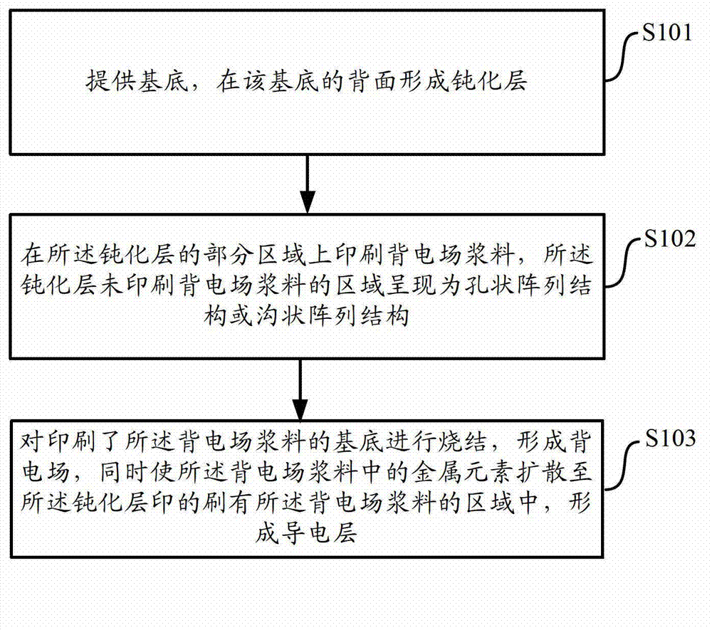
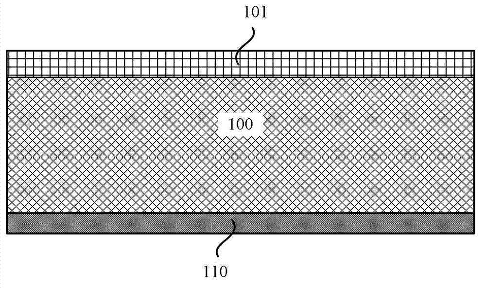
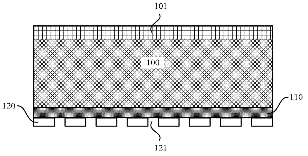
The invention discloses a preparation method of a back surface field of a back-passivated solar cell. The preparation method comprises the following steps. A base is provided, and a passivating layer is formed at the back of the base. Back surface field size is printed on part of the passivating layer, and an area, not being printed with the back electric size, of the passivating layer is of a hole-shaped array structure or a ditch-shaped array structure. Sintering of the base printed with the back surface field size is performed so as to form the back surface field, and meanwhile metal elements in the back surface field size are spread to the area printed with the back surface field size of the passivating layer so as to form a conductive layer. Accordingly, the invention also provides the passivating solar cell provided with the back surface field. The preparation method of the back surface field of the back-passivated solar cell and the back-passivated solar cell provided with the back surface field is capable of effectively simplifying preparation technology of the passivated solar cell, increasing toughness of the solar cell and reducing production cost of the solar cell.

Description

technical field [0001] The invention relates to the field of solar cells, in particular to a method for preparing a back electric field of a back passivated solar cell and a back passivated solar cell with the back electric field. Background technique [0002] In the traditional process, the steps of preparing the back passivation solar cell back electric field are as follows: (a) provide a substrate (usually a silicon wafer), and form a passivation layer on the back side of the substrate (used to form the backlight surface of the solar cell) (b) opening holes on the passivation layer to expose part of the passivation layer by means such as laser etching or wet etching; (c) printing back electric field paste on the passivation layer, wherein there will be some The back electric field paste enters the opening; (d) sintering the substrate printed with the back electric field paste to form a back electric field, and the part entering the opening forms a good ohmic contact with ...

Claims


Application Information

Patent Timeline
IPC IPC(8): H01L31/18H01L31/0216H01L31/0224
CPCY02P70/50
Inventor 唐兆俊单伟韩玮智牛新伟蒋前哨李永辉仇展炜
Owner CHINT NEW ENERGY TECH (HAINING) CO LTD
Why Eureka
Try Eureka