Performance test device and method of general servo mechanism based on universal serial bus (USB)
A technology of servo mechanism and test device, applied in electrical testing/monitoring and other directions, can solve the problems of high cost and large volume
- Summary
- Abstract
- Description
- Claims
- Application Information
AI Technical Summary
Problems solved by technology
Method used
Image
Examples
specific Embodiment approach 1
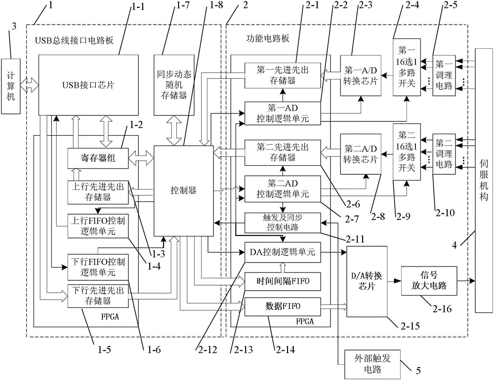
[0059] Specific implementation mode one: the following combination figure 1 Illustrate this embodiment, the universal servomechanism performance testing device based on USB bus described in this embodiment, it comprises computer 3, and it also comprises USB bus interface circuit board 1 and function circuit board 2,
[0060] The USB bus interface circuit board 1 includes a USB interface chip 1-1, a register set 1-2, an uplink FIFO control logic unit 1-4, an uplink FIFO control logic unit 1-4, a downlink FIFO control unit, and a downlink FIFO control unit. logic unit 1-6, synchronous dynamic random access memory 1-7 and controller 1-8,
[0061] The functional circuit board 2 includes a first FIFO memory 2-1, a first AD control logic unit 2-2, a first A / D conversion chip 2-3, a first 16-selection multiplexer 2-4, a first Conditioning circuit 2-5, second FIFO memory 2-6, second AD control logic unit 2-7, second A / D conversion chip 2-8, second 16-to-1 multiplexer 2-9, the second ...
specific Embodiment approach 2
[0079] Specific implementation mode two: the following combination figure 1 , Figure 7 and Figure 8 Describe this embodiment, this embodiment is a further description of Embodiment 1, this embodiment also includes an external trigger circuit 5, the trigger signal output end of the external trigger circuit 5 is connected to the trigger signal input end of the trigger and synchronization control circuit 2-11 .
[0080] Figure 7 As shown, in order to ensure the reliability and anti-interference of the signal, the EXTRG_IN signal passes through the switching transistor in turn, and is output after the optocoupler. Pin 4 of the optocoupler is connected to a 3.3V power supply through a pull-up resistor in order to be compatible with the FPGA IO port level. When EXTRG_IN is high level, the triode is turned on, so that the light-emitting diode between the input terminals 1 and 2 of the optocoupler TLP521 is turned on, and the optocoupler 4 pin outputs a low level, and the EXTRG...
specific Embodiment approach 3
[0082] Embodiment 3: This embodiment is a further description of Embodiment 1 or 2. The controller 1-8 in this embodiment is a TMS320VC3 floating-point DSP chip.
PUM
 Abstract
Description
Claims
Application Information
 - R&D
- Intellectual Property
- Life Sciences
- Materials
- Tech Scout
- Unparalleled Data Quality
- Higher Quality Content
- 60% Fewer Hallucinations
Browse by: Latest US Patents, China's latest patents, Technical Efficacy Thesaurus, Application Domain, Technology Topic, Popular Technical Reports.
© 2025 PatSnap. All rights reserved.Legal|Privacy policy|Modern Slavery Act Transparency Statement|Sitemap|About US| Contact US: help@patsnap.com


