Long-distance micro/nano-core glass optical fiber and preparation method thereof
A glass fiber and nano-core technology, applied in the field of micro-nano optical devices, can solve the problems of difficulty in large-scale production, limited length of micro-nano fibers, etc., and achieve the effects of controllable fiber structure size, wide selection range, and stable process.
- Summary
- Abstract
- Description
- Claims
- Application Information
AI Technical Summary
Problems solved by technology
Method used
Image
Examples
Embodiment 1
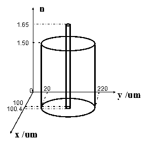
[0014] Example 1 (eg figure 2 shown) :
[0015] (1) Doped with Tb 3+ Phosphate glass-clad lumps are put into the extruder (the lumps have a refractive index of 1.50, a diameter of 80 mm, and a length of 100 mm, Tb 3+ The concentration is 8.6×10 20 cm -3 ), extrude a casing with an inner diameter of 3 mm and an outer diameter of 21 mm at 600 °C;
[0016] (2) Put the phosphate glass core material with a refractive index of 1.65 into the wire drawing machine, and draw a core rod with a diameter of 3 mm at 600 °C;
[0017] (3) Insert a core rod with a diameter of 3 mm into a casing with an inner diameter of 3 mm and an outer diameter of 21 mm, and shrink it by 7 times at 600 °C through a wire drawing machine to obtain a combined glass rod tube A with an inner diameter of 428 μm and an outer diameter of 3 mm ;
[0018] (4) Insert the combined glass rod tube A into the casing with an inner diameter of 3 mm and an outer diameter of 21 mm, and shrink it by 7 times through a ...
Embodiment 2
[0021] (1) will be doped with Yb 3+ The phosphate glass-clad lump is put into the extruder (the lump has a refractive index of 1.50, a diameter of 100 mm, and a length of 150 mm, Yb 3+ The concentration is 8.3×10 20 cm -3 ), at 600 °C extrude a casing with an inner diameter of 3 mm and an outer diameter of 18 mm;
[0022] (2) Put the phosphate glass core material with a refractive index of 1.65 into the wire drawing machine, and draw a core rod with a diameter of 3 mm at 600 °C;
[0023] (3) Insert a core rod with a diameter of 3 mm into a casing with an inner diameter of 3 mm and an outer diameter of 18 mm, and shrink it by 6 times through a wire drawing machine at 600 °C to obtain a combined glass rod tube A with an inner diameter of 500 μm and an outer diameter of 3 mm ;
[0024] (4) Insert the combined glass rod tube A into the casing with an inner diameter of 3 mm and an outer diameter of 18 mm, and shrink it by 6 times through a wire drawing machine at 600 °C to obt...
Embodiment 3
[0027] (1) Will be doped with Nd 3+ The phosphate glass-clad lump is put into the extruder (the lump has a refractive index of 1.52, a diameter of 100 mm, a length of 150 mm, Nd 3+ The concentration is 2×10 19 cm -3 ), at 600 °C extrude a casing with an inner diameter of 3 mm and an outer diameter of 25 mm;
[0028] (2) Take Nd-doped again 3+Put the phosphate glass cladding lump into the extruder, and extrude a casing with an inner diameter of 4 mm and an outer diameter of 25 mm at 600 °C;
[0029] (3) Take Nd-doped for the third time 3+ Put the phosphate glass cladding lump into the extruder, and extrude a casing with an inner diameter of 5 mm and an outer diameter of 30 mm at 600 °C;
[0030] (4) Put the phosphate glass core material with a refractive index of 1.68 into the extruder, and extrude a core rod with a diameter of 4 mm at 600 °C;
[0031] (5) Insert a core rod with a diameter of 4 mm into a casing with an inner diameter of 4 mm and an outer diameter of 25 m...
PUM
| Property | Measurement | Unit |
|---|---|---|
| diameter | aaaaa | aaaaa |
| diameter | aaaaa | aaaaa |
| length | aaaaa | aaaaa |
Abstract
Description
Claims
Application Information
 - R&D
- Intellectual Property
- Life Sciences
- Materials
- Tech Scout
- Unparalleled Data Quality
- Higher Quality Content
- 60% Fewer Hallucinations
Browse by: Latest US Patents, China's latest patents, Technical Efficacy Thesaurus, Application Domain, Technology Topic, Popular Technical Reports.
© 2025 PatSnap. All rights reserved.Legal|Privacy policy|Modern Slavery Act Transparency Statement|Sitemap|About US| Contact US: help@patsnap.com


