
Permanent magnet reluctance type in-wheel motor

A hub motor and reluctance technology, applied in the field of permanent magnet reluctance type outer rotor hub motor, can solve the problems of not mentioning reluctance torque, large rotor surface loss, large torque ripple and positioning torque, etc., to simplify The effect of high frequency injection rotor position signal extraction algorithm, improving system reliability and improving product reliability

Inactive Publication Date: 2013-03-27
吴正林
View PDF6 Cites 19 Cited by
  • Summary
  • Abstract
  • Description
  • Claims
  • Application Information

AI Technical Summary

Problems solved by technology

Ordinary electric bicycles mainly use the outer rotor brushless DC hub motor, which adopts a surface-mounted hidden pole structure, such as the rotor structure disclosed in the Chinese utility model patent "Electric Wheel Hub Motor" with the patent number ZL200820082308.5. This type of hidden pole motor The torque is derived from the electromagnetic torque, so a large amount of rare earth permanent magnets are required. The magnets required by this patent are closely pasted with N poles and S poles alternately. In fact, the adjacent areas where the two kinds of magnets are closely pasted The magnetic force lines are directly connected without coupling to the rotor, and the brushless motor realizes a 120° conduction mode, so it is a waste to place the magnetic steel closely, but the production process of the magnetic steel mounting is simple
Another example is the Chinese utility model "Adhesive magnetic steel ring between rotors of electric vehicle motor" with patent No. 201020049324.1, which discloses such a structure. It is proposed to use the boss to control the installation of the magnetic steel. Although the amount of the magnetic steel is reduced, the motor cannot be driven by the reluctance torque.
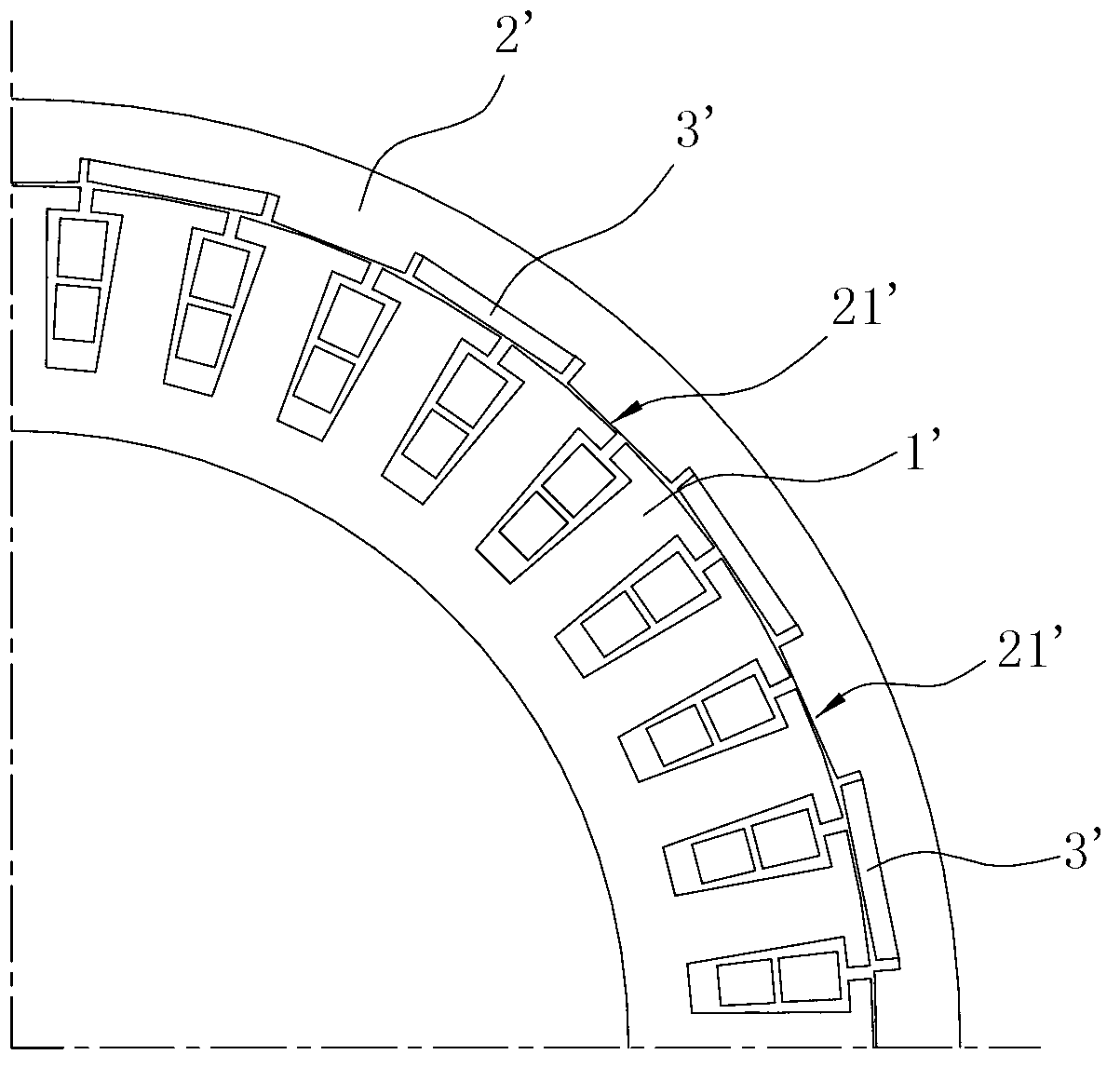
[0004] In addition, the Chinese invention application "Electric Vehicle Motor" with the application number of 201110061396.7 discloses a method for reducing the amount of magnets used in brushless motors of electric vehicles, reducing the number of magnets by half, and only installing magnets of the same polarity. Using the salient pole magnetically conductive convex body, it is claimed that the amount of magnetic steel can be greatly reduced, but this method is specified to be used for brushless motors. The operation of brushless motors requires a certain amount of magnetic flux, and the air gap magnetic flux density must meet the requirements for torque generation. The permanent magnet is used as the excitation source, and only one polarity of the magnet is used. The magnet must be thickened and widened. The actual saving effect may not exceed the former; secondly, the magnetic circuit of the patented motor is no longer symmetrical , has the ability to generate reluctance torque, but the patent does not mention the use of reluctance torque (it must be realized through a suitable control method, such as FOC control strategy); in addition, there is another problem in this patent The problem is that the magnetically conductive salient pole adopts a rectangular structure, and its shape has a great influence on the torque. When the rotor salient pole and the stator tooth top move in and out relative to each other, a large torque ripple and positioning torque will be generated, resulting in Phase torque pulsation noise is large, and the surface of the rotor is easy to wear, which affects its application effect on electric vehicles
[0005] At present, electric vehicle motors still use brushless DC motors and related control methods. In this method, the position of the rotor is obtained by the Hall position detector, and the three-phase windings are commutated and turned on in turn. The control method is simple, but there is a commutation Disadvantages such as large torque ripple noise and large rotor surface loss
Algorithms represented by control schemes such as FOC and DTC have realized sine wave drive control, and the motor magnetic field has changed from a stepping method of brushless DC to a continuous and smooth operation mode, with stable rotation and high efficiency, and can make good use of the motor reluctance rotation. Torque, increasing the output or reducing the amount of magnetic steel has been considered as the development direction of electric bicycle drive control. However, this kind of high-performance control has higher requirements for the detection accuracy of the rotor position. Installing an encoder on the electric bicycle to detect the position, due to the cost The problem appears unrealistic and cannot be accepted by the market
In addition, permanent magnet motors with salient polarity can easily implement position sensorless control technology, which saves position detection components, reduces system cost and increases reliability. However, since position sensorless control technology is generally aimed at sine wave driven Permanent magnet synchronous motors have certain requirements on motor inductance, and it is difficult to apply salient pole brushless DC motors without optimization

Method used


Image

  • Permanent magnet reluctance type in-wheel motor
  • Permanent magnet reluctance type in-wheel motor
  • Permanent magnet reluctance type in-wheel motor

Examples


Embodiment Construction

[0021] The present invention will be further described in detail below in conjunction with the accompanying drawings and embodiments.

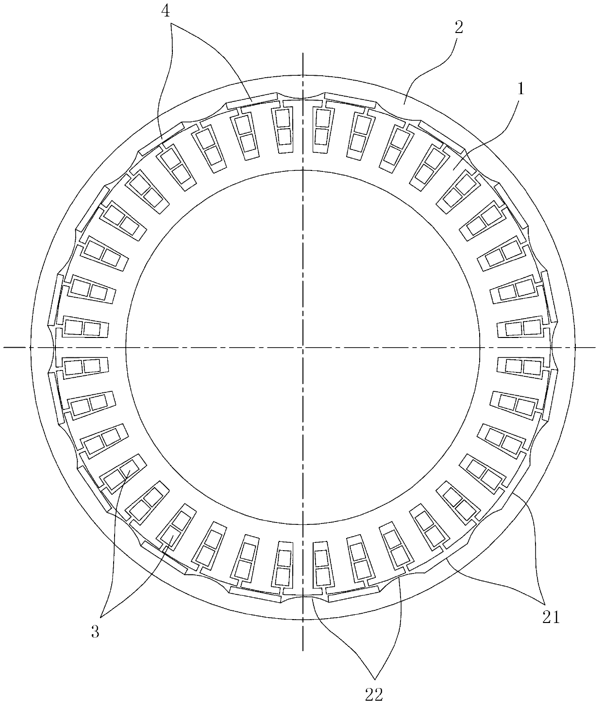
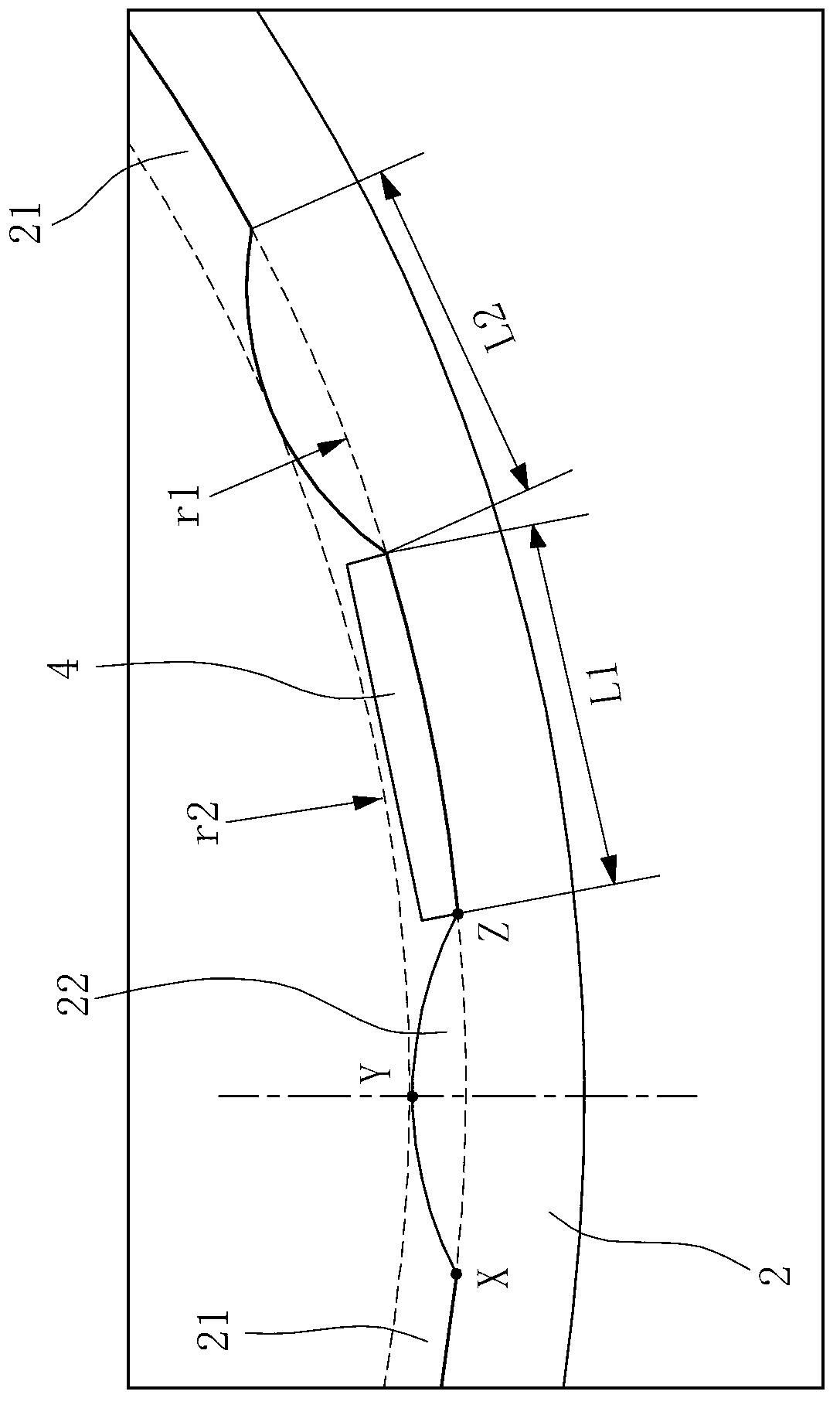
[0022] Such as figure 1 , figure 2 As shown, this embodiment is a permanent magnet reluctance hub motor for electric bicycles. The motor adopts an outer rotor structure, including an inner stator 1, an outer rotor 2, a shaft and a hub shell, and the inner stator 1 is fixed on the shaft. , the outer rotor 2 is fixed on the hub shell, the structure of the shaft and the hub shell is the same as that of the conventional electric bicycle motor, the stator core is the same as the stator structure of the conventional outer rotor brushless DC motor, and the inner stator 1 of this embodiment is 36 slots (teeth) are evenly distributed, the stator winding 3 is symmetrically distributed in three phases, and the phase difference is 120 degrees.

[0023] The outer rotor 2 of this embodiment is formed with grooves 21 arranged at intervals on the inner per...


PUM


Abstract

The invention relates to a permanent magnet reluctance type in-wheel motor, which comprises an outer rotor and an inner stator, wherein a three-phase winding is arranged on the inner stator; magnetic steel is uniformly distributed along the circumferential direction of the outer rotor; the permanent magnet reluctance type in-wheel motor is characterized in that grooves arranged at intervals are formed on the inner circumferential surface of the outer rotor; the magnetic steel is embedded inside the grooves; the cross section of the magnetic steel is rectangular; the polarity of all magnetic steel facing to the inner stator is the same; a magnetic conduction salient pole is formed between adjacent grooves; the magnetic conduction salient poles and the magnetic steel are arranged alternately at intervals; the curve of the cross section of the magnetic conduction salient pole facing to one side end of the inner stator is convex arc-shaped; and the number of grooves and the number of magnetic poles in the outer rotor adopt the combination with close grooves. The permanent magnet reluctance type in-wheel motor has the advantages that the using amount of magnetic steel can be efficiently reduced and the output of reluctance torque is improved under the precondition of not increasing process complexity; and the magnetic conduction salient poles adopt arc-shaped convex surfaces, so that the motor torque pulsation is efficiently reduced, the stability of motor running is ensured, and the product reliability is improved.

Description

technical field [0001] The invention relates to a permanent magnet reluctance motor, in particular to a permanent magnet reluctance outer rotor hub motor applicable to electric bicycles or electric motorcycles. Background technique [0002] The permanent magnet motor uses permanent magnets to generate the magnetic field of the motor. It does not require excitation coils or excitation current. It has high efficiency and simple structure. It is a good energy-saving motor and is often used as the first choice for driving electric bicycles. [0003] In 2012, the number of electric bicycles in China reached 140 million, and the annual growth rate is about 30 million. Ordinary electric bicycles mainly use the outer rotor brushless DC hub motor, which adopts a surface-mounted hidden pole structure, such as the rotor structure disclosed in the Chinese utility model patent "Electric Wheel Hub Motor" with the patent number ZL200820082308.5. This type of hidden pole motor The torque i...

Claims


Application Information

Patent Timeline
IPC IPC(8): H02K1/27H02P6/18H02P6/10
Inventor 黄文新吴正林
Owner 吴正林
Learn More