Motor-driven steam mop
A steam and electric technology, used in manual floor scrubbing machinery, carpet cleaning, household appliances, etc., can solve the problems of low efficiency and impracticality, low machine power, and high speed of the motor 6, so as to reduce heavy housework and reduce volume. , the effect of flexible speed
- Summary
- Abstract
- Description
- Claims
- Application Information
AI Technical Summary
Problems solved by technology
Method used
Image
Examples
Embodiment
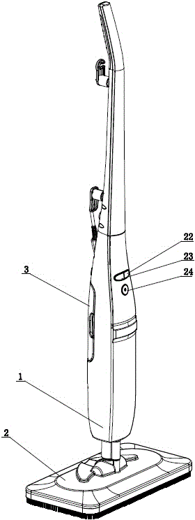
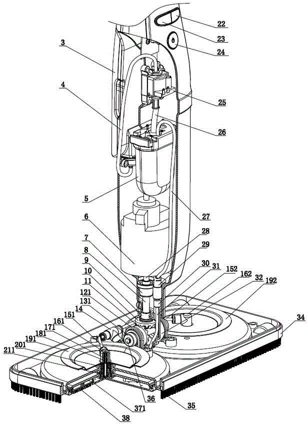
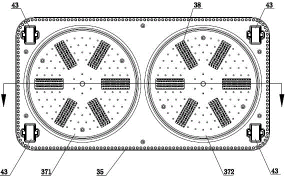
[0031] The structure diagram of the present invention is as figure 1 , 2 , 3, and 4, the electric steam mop of the present invention includes a handle (1), a mop head (2) mounted on the lower part of the handle (1), a mopping mechanism mounted on the mop head (2), An electric system that drives the movement of the mopping mechanism and a steam system that delivers steam to the mopping mechanism, wherein the electric system is installed on the handle (1), and the electric system is connected to the mopping mechanism through a transmission mechanism.
[0032]The above-mentioned mop head 2 includes a connector 32 and a mop head seat 34. The connector 32 can be a part that can be detached from the handle 1, or can be a part of the handle 1 that cannot be detached from the handle 1. In order to make the floor mop easier to clean, the present invention preferentially makes the connecting head 32 detachable from the handle 1. In this way, after the floor mop is removed, there is no ...
Embodiment 2
[0051] Such as Figure 7 As shown, in this embodiment, the bevel gear pair in the connecting head 32 of the first embodiment is replaced by a worm gear transmission mechanism, the worm 47 replaces the input shaft 8 and the driving bevel gear 10, the worm wheel 45 replaces the driven bevel gear 11, and the worm 47 coincides with the connecting shaft 44 of the connecting head 32, the worm wheel 45 is connected with the output shaft 36, and the output shaft 36 coincides with the rotating shaft 33 of the connecting head 32. After the handle 1 is connected to the connector 32 of the mop head 2, the motor shaft 28 of the motor 6 is connected to the male shaft connector 42 at the shaft end of the worm 47 through the female shaft connector 7 at the shaft end. Obviously, the two shafts of the bevel gear pair in Embodiment 1 intersect with an included angle of 90°, while the shaft of the worm wheel 45 in Embodiment 2 does not intersect with the worm shaft (that is, the output shaft 36 )...
Embodiment 3
[0054] Such as Figure 9 , this embodiment uses a pair of friction wheels to replace the bevel gear pair in the connecting head 32 of the first embodiment. This embodiment adopts conical friction wheel transmission, and the friction wheel transmission needs to apply pressure between the friction wheels. A pressure spring 50 is arranged between the active conical friction wheel 48 and the bearing. Under the effect of the pressure spring 50, the active conical friction wheel 48 and the driven conical friction wheel 49 are compressed, and the two conical friction wheels Appropriate frictional force has been produced between them, and when the active conical friction wheel 48 rotates, it drives the driven conical friction wheel 49 to rotate, and its effect is consistent with that of the bevel gear pair in Embodiment 1, and the direction of transmission is also changed. And also can change the transmission speed according to need. The connecting head 32 of this embodiment is drive...
PUM
 Abstract
Description
Claims
Application Information
 - R&D
- Intellectual Property
- Life Sciences
- Materials
- Tech Scout
- Unparalleled Data Quality
- Higher Quality Content
- 60% Fewer Hallucinations
Browse by: Latest US Patents, China's latest patents, Technical Efficacy Thesaurus, Application Domain, Technology Topic, Popular Technical Reports.
© 2025 PatSnap. All rights reserved.Legal|Privacy policy|Modern Slavery Act Transparency Statement|Sitemap|About US| Contact US: help@patsnap.com


