Method and device for purifying liquid ammonia decomposition gas
A purification method and a technology for decomposing gas, which are applied in the directions of using liquid contact hydrogen separation, hydrogen separation, hydrogen production, etc., which can solve the problems of reduced performance of cemented carbide and great influence of cemented carbide performance.
- Summary
- Abstract
- Description
- Claims
- Application Information
AI Technical Summary
Problems solved by technology
Method used
Image
Examples
Embodiment 1
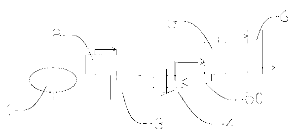
[0024] The following describes the purification method of the liquid ammonia decomposition gas described in the application for the invention with reference to the device, and the method includes the following steps:
[0025] 1. Liquid ammonia vaporization: liquid ammonia is stored in the liquid ammonia storage tank, and is vaporized through the liquid ammonia evaporator in the vaporization chamber and the buffer storage tank. The liquid ammonia enters the liquid ammonia evaporator and contacts the heat exchange fins, so that the temperature of the liquid ammonia rises. Vaporization is carried out at a temperature of up to 20°C, the pressure is controlled at 0.2Mpa, the heat exchange source is water vapor, and the liquid ammonia enters the buffer storage tank after vaporization to maintain a stable supply of ammonia gas, and the outlet pressure is controlled to 0.3 Mpa by a pressure reducing valve;
[0026] 2. Ammonia decomposition: After the liquid ammonia is vaporized, it is ...
Embodiment 2
[0031] Described method comprises the steps:
[0032]1. Liquid ammonia vaporization: liquid ammonia is stored in the liquid ammonia storage tank, and is vaporized through the liquid ammonia evaporator in the vaporization chamber and the buffer storage tank. The liquid ammonia enters the liquid ammonia evaporator and contacts the heat exchange fins, so that the temperature of the liquid ammonia rises. The temperature is as high as 40°C for vaporization, the pressure is controlled at 0.5Mpa, the heat exchange source is hot water, and the liquid ammonia enters the buffer storage tank after vaporization to maintain a stable supply of ammonia gas, and the outlet pressure is controlled to 0.4 Mpa through the pressure reducing valve;
[0033] 2. Ammonia decomposition: After the liquid ammonia is vaporized, it is decomposed in the ammonia decomposition furnace. The ammonia decomposition furnace is composed of a preheater and a catalytic decomposer. The gas enters the catalytic decompo...
Embodiment 3
[0038] Described method comprises the steps:
[0039] 1. Liquid ammonia vaporization: liquid ammonia is stored in the liquid ammonia storage tank, and is vaporized through the liquid ammonia evaporator in the vaporization chamber and the buffer storage tank. The liquid ammonia enters the liquid ammonia evaporator and contacts the heat exchange fins, so that the temperature of the liquid ammonia rises. The temperature is as high as 30°C for vaporization, the pressure is controlled at 0.3Mpa, the heat exchange source is hot water, and the liquid ammonia enters the buffer storage tank after vaporization to maintain a stable supply of ammonia gas, and the outlet pressure is controlled to 0.4 Mpa by a pressure reducing valve;
[0040] 2. Ammonia decomposition: After the liquid ammonia is vaporized, it is decomposed in the ammonia decomposition furnace. The ammonia decomposition furnace is composed of a preheater and a catalytic decomposer. The gas enters the catalytic decomposer, i...
PUM
| Property | Measurement | Unit |
|---|---|---|
| thickness | aaaaa | aaaaa |
| thickness | aaaaa | aaaaa |
| thickness | aaaaa | aaaaa |
Abstract
Description
Claims
Application Information
 - R&D
- Intellectual Property
- Life Sciences
- Materials
- Tech Scout
- Unparalleled Data Quality
- Higher Quality Content
- 60% Fewer Hallucinations
Browse by: Latest US Patents, China's latest patents, Technical Efficacy Thesaurus, Application Domain, Technology Topic, Popular Technical Reports.
© 2025 PatSnap. All rights reserved.Legal|Privacy policy|Modern Slavery Act Transparency Statement|Sitemap|About US| Contact US: help@patsnap.com

