current mode isolated converter

A converter and current-type technology, which is applied in the field of current-mode insulated converters, can solve problems such as reduced efficiency and increased heat generation, and achieves the effect of easy design and suppressed voltage rise

Active Publication Date: 2016-06-15
TDK CORPARATION
View PDF7 Cites 0 Cited by
  • Summary
  • Abstract
  • Description
  • Claims
  • Application Information

AI Technical Summary

Problems solved by technology

However, in a general RCD snubber circuit formed of a resistor (R), capacitor (C) and diode (D), efficiency decreases and heat generation increases

Method used


Image

  • current mode isolated converter
  • current mode isolated converter
  • current mode isolated converter

Examples


Embodiment Construction

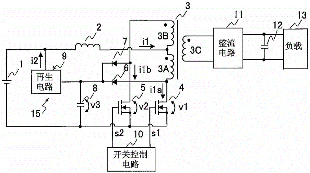
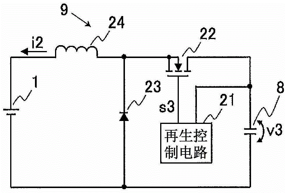
[0044] The operation of the DCDC converter including the snubber circuit according to the present invention will be described with reference to the drawings. figure 1 An embodiment of a DCDC converter including a snubber circuit according to the present invention is shown. The DCDC converter of this embodiment is a current-source isolated converter including a choke coil (choke coil) 2 . This DCDC converter is composed of a transformer 3 , a primary side circuit provided on the primary side of the transformer 3 , and a secondary side circuit provided on the secondary side of the transformer 3 . The transformer 3 includes a primary coil 3A, a primary coil 3B, and a secondary coil 3C. The primary side circuit is composed of a choke coil 2 , FET (Field Effect Transistor) 4 , FET 5 , switch control circuit 10 , and snubber circuit 15 . Snubber circuit 15 is composed of diode 6 , diode 7 , capacitor 8 and regenerative circuit 9 . The secondary side circuit is constituted by a re...


PUM


Abstract

The present invention provides a current source isolated converter that is easy to design and includes a regenerative snubber circuit that operates stably. It is a current-source insulated converter including a choke coil (2) connected to the primary side of a transformer (3) and FETs (4, 5) that control the current flowing through the choke coil (2), and includes a snubber circuit (15 ) and the regenerative circuit (9) as a step-down power supply circuit, the snubber circuit (15) is composed of diodes (6, 7) and capacitors (8), and when any one of the FETs (4, 5) is off, the capacitor (8 ) to suppress the overvoltage applied between the drain and source of the FET (4, 5). In addition, the regenerative circuit (9) regenerates the charge charged in the capacitor (8) by the DC power supply (1) as the power supply for supplying electric power to the primary side of the transformer (3), and operates to regenerate the charged charge of the capacitor (8). The voltage is maintained at the specified voltage value.

Description

technical field [0001] The present invention relates to a current-source insulating converter, and more particularly, to a current-source insulating converter including a snubber circuit that regenerates energy stored in a snubber capacitor on an input side. Background technique [0002] In Patent Document 1, a current-mode insulating converter is disclosed. In such a current-mode isolated converter, when the switching element is turned off, an excessive voltage is applied to the switching element. In order to prevent this excessive voltage from being applied to the switching element, a snubber circuit is generally used. However, in a general RCD snubber circuit formed of a resistor (R), capacitor (C) and diode (D), efficiency decreases and heat generation increases. In order to solve such a problem, Patent Document 2 discloses a snubber circuit that regenerates energy stored in a snubber capacitor on the input side. [0003] patent documents [0004] Patent Document 1: ...

Claims


Application Information

Patent Timeline
Patent Type & Authority Patents(China)
IPC IPC(8): H02M3/335H02M1/34
CPCH02M3/335H02M3/3374H02M1/34
Inventor 竹上荣治
Owner TDK CORPARATION
Why Eureka
Try Eureka