
Mixed congestion control method based on packet loss and time delay

A congestion control and packet loss technology, applied in digital transmission systems, electrical components, transmission systems, etc., can solve the problems of maintaining the same and unable to respond to the current status of internal network congestion in a timely manner, and achieve guaranteed adjustment and long-latency network transmission performance. Improve the effect of general applicability

Active Publication Date: 2013-01-16
SICHUAN UNIV
View PDF3 Cites 34 Cited by
  • Summary
  • Abstract
  • Description
  • Claims
  • Application Information

AI Technical Summary

Problems solved by technology

However, the congestion control method based on packet loss simply modifies the window adjustment parameters in the congestion avoidance phase; in congestion detection, it mainly estimates the network congestion and its severity based on the ACK feedback at the receiving end and the RTO timer at the source end, and does not fundamentally solve how to improve the network Congestion detection accuracy problem: For example, the CUBIC congestion control protocol with good transmission performance has superior performance in terms of throughput and RTT fairness, but its network steady-state window value remains unchanged between two packet loss periods, and cannot respond to the network in a timely manner. Internal congestion status
However, in the actual environment, RTT estimation will be affected by many noises, resulting in an increase in error and affecting the judgment of the current network status. Therefore, relying entirely on RTT to adjust the congestion window has brought a series of problems: Fast TCP adjusts the congestion window based on RTT, and there are the above errors question

Method used


Image

  • Mixed congestion control method based on packet loss and time delay
  • Mixed congestion control method based on packet loss and time delay
  • Mixed congestion control method based on packet loss and time delay

Examples


Embodiment Construction

[0047] The present invention will be further described below in conjunction with the drawings and specific implementation process.

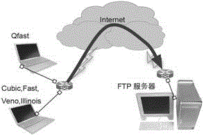
[0048] First refer to Figure 5 That is, the test environment configuration diagram of the present invention sets up the operating environment: two configuration FTP clients and respectively configure the operating system (the test environment of the present invention is the UBUNTU system) of QFast of the present invention and other congestion control protocols (Illinois, Veno, Fast), configure Remote FTP server, two FTP clients, upload files to FTP server at the same time

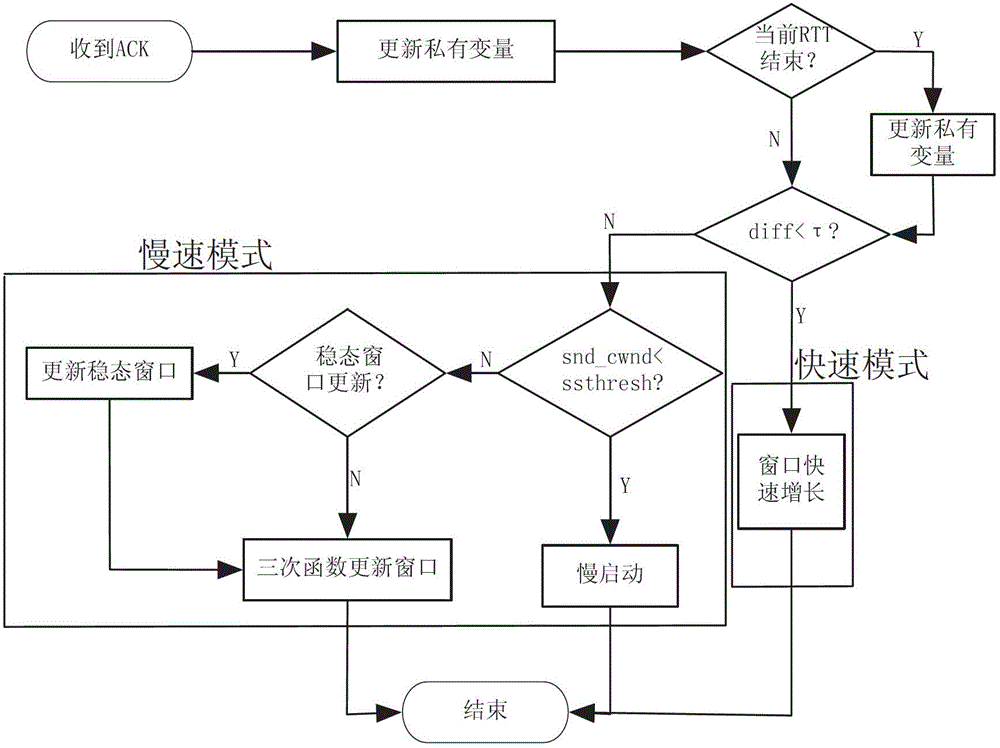
[0049] refer to figure 1 That is, the flow chart of the QFast congestion control method described in the present invention, after the TCP connection is established, the steps of the congestion control method are as follows:

[0050] Step 1: Whenever the TCP connection source receives a new ACK from the receiver, it updates the QFast private state variable: refers to the cur...


PUM


Abstract

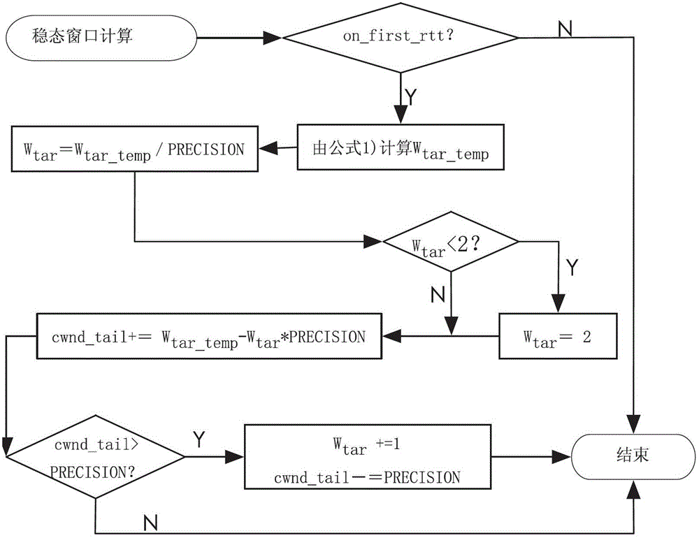
A mixed congestion control method based on packet loss and time delay comprehensively gives consideration to network packet loss and time delay information and conducts mixed mode control on congestion windows. Adjustment of the congestion windows is based on improvement of Fast congestion control in a fast mode. In a slow mode, a current network steady state window value is calculated according to network states at round-trip time interval, and then congestion control strategies based on CUBIC improvement is carried out. The mixed congestion control method comprehensively uses congestion control superiorities based on the time delay and the packet loss and adopts a mixed strategy to conduct congestion control, and a congestion window adjustment mode combining the two modes guarantees that the congestion windows rapidly achieve and continuously maintain a network steady state value. An improved congestion control algorithm can rapidly and effectively adjust the congestion control windows on a transport layer under high bandwidth, improve transmission throughput rate of a network flow and simultaneously guarantee a network to be stable.

Description

technical field [0001] The invention belongs to a reliable transmission method of a computer network, in particular to a mixed congestion control method based on packet loss and time delay suitable for high-bandwidth and long-time-delay networks. Background technique [0002] The congestion control method proposed by Jacobson in 1986 effectively solved the problem of network congestion control. However, with the development of the new generation of Internet in the direction of high speed and wireless, and the emergence of network applications such as satellites, aviation, astronomical observation, high-energy physics and other massive scientific research data transmission requirements, the traditional TCP (transmission control protocol) can no longer meet the growing transmission need. In order to adapt to the data transmission performance in high-speed long-delay networks, researchers have proposed a variety of congestion control mechanisms, mainly including congestion con...

Claims


Application Information

Patent Timeline
IPC IPC(8): H04L12/807H04L12/823H04L12/825H04L12/841H04L47/27H04L47/32
Inventor 王俊峰许建利王敏
Owner SICHUAN UNIV
Learn More